
Installation Guide


7
FP9K-DX-XLT
Jan 2019
INSTALLATION INSTRUCTIONS
Improper installation can cause accelerated wear, resulting in catastrophic failure which may cause
property damage and / or bodily injury. Manufacturer will assume no liability for loss or damage of any
kind, expressed or implied, resulting from improper installation or use of this product. Read this
installation manual in its entirety before attempting to install or operate the lift.
1. Remove plastic wrap from top Runway and remove all hardware. This includes the Power Unit,
‘wire braded’ Hydraulic Hose and Hardware Box.
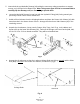
2. While the Mainside Runway (Fig. 2) is upside down, find the end of the Hydraulic Hose that is
already connected to the Cylinder. Locate hole on the side of the Mainside Runway (#1) and
install the 90 degree Fitting (#61) securing to runway with Jam Nut. Also remove the plastic
shipping ties securing the pre-installed Cables.
3. With the Mainside Runway upside down, pull to extend the Cable Ends through the holes on
each end of the Runway. Also, ensure the hydraulic fittings are tightened.
Fig. 2
4. Fully extend the Cylinder Piston Rod by pushing or pulling on the Cable Lock Plates (#41 &
#42) mounted on the end of the Cylinder.
90 degree
Fitting w/
Jam Nut
Mainside Runway
(upside down)
Cylinder Hose
Cylinder Piston
Rod
Cable Lock
Plates
‘Wire braded’ Hose