
User Manual

Setup:
1. To prepare the transmitter for binding information refer to your transmitter’s user manual.
2. Supply power to the receiver. When the receiver is rst powered on it will remain in bind mode for 5
seconds.
• After successfully binding,the transmitter will then automatically return to the previous menu.
USER MANUAL (FS-iA6C)
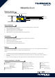
Receiver overview
The transmitter and receiver have been pre-bound before delivery. If you are using another transmitter or
receiver, use the steps below to complete the binding process.
Receiver specification (TGY-iA6C)
channels: 8
Model type: Quadcopter/
Fixed-wing/
Helicopter
RF range: 2.408-2.475GHz
RF channel: 135
RX sensitivity: -105dbm
2.4GHz system: AFHDS 2A
Modulation type: GFSK
Power input: 4.0V-6.5V DC
Weight: 7.9g
Antenna length: 26mm*2
Size: 37.5×24.2×9.0mm
Color: Black
i-BUS port: Yes
Data acquisition port: Yes
Certicate: CE0678, RCM,
FCC ID:N4ZIA6C00
Status indicator
Update indicator
Antenna
PPM
S.BUS/i-BUS
Power input
Alternate power input (0-20V)
Binding
Status Indicator
Connectors
The status indicator is used to indicate the power and working status of the receiver.
• Off: the power is not connected.
• Lit in red: the receiver is on and working.
• Flashing quickly: the receiver is binding.
• Flashing slowly: the bound transmitter is off or signal is lost.
The connectors are used to connect the parts of model and the receiver.
• PPM: Outputs standard PPM signal.
• GND/VCC: Power Input.
• S.BUS / i-BUS: S.BUS and i.BUS Interface.
• B-DET: Alternative port for powering receiver.
FCC ID:N4ZIA6C00