
User Manual


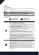

2.2.1 Transmitter Antenna
Precautions:
• For best signal quality, make sure that the antenna is at about a 90 degree angle to the model. Do not
point the antenna directly at the receiver.
• Never grip the transmitter antenna during operation. It significantly degrades the RF signal quality
and strength and may cause loss of control.
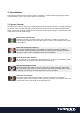
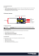
2.3 Receiver Overview
Status Indicator Update Indicator
2.3.1 Receiver Antenna
Attention
· For best signal quality, ensure that the receiver is mounted away from motors
or metal parts.
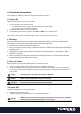
2.3.2 Status Indicator
The status indicator is used to indicate the power and working status of the receiver.
• Off: the power is not connected.
• Lit in red: the receiver is on and working.
• Flashing quickly: the receiver is binding.
• Flashing slowly: the bound transmitter is off or signal is lost.
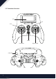
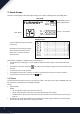
2.3.3 Connectors
The connectors are used to connect the parts of model and the receiver.
• PPM: Channel output
• GND/VCC: Power Input
• S.BUS: S.BUS and i.Bus Interface
• B-DET: Alternative port for powering receiver.
Antenna
Ground
S.BUS/iBUS
PPM
Alt Power Input
(0 -- 20V)
VCC