
User Manual

Manual of Program Card Doc Ver. HW-02-080623.1
USER MANUAL OF PROGRAM CARD
1
Thank you for purchasing program card for the brushless motor electronic speed controller
(ESC). With this device, you can easily set the programmable value of the ESC. Now you
can just forget the complex and boring program method with the throttle stick of your
transmitter. This
program card has a friendly user interface. It is as small as a business
card, so you can put it in your pocket when you are on the field.
SPECIFICATION:
1. SIZE: 92mm * 52mm * 6mm
2. WEIGHT: 26g
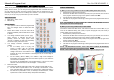
FRONT PANEL:
1. Use “up/down” button to select the programmable
item, use “left/right” button to select each item
value;
2. Brake: When “Brake” is ON, the motor will be
stopped immediately when throttle stick is moved
to bottom;
3. Low Voltage Protection Mode (Cut-off Type):
When “Soft-Cut” is selected, the ESC will
gradually reduce the output power. When
“Cut-Off” is selected, the ESC will immediately
shut off the output power to the motor.
4. Low Voltage Protection Threshold (Cut-off
Voltage):
For Li-xx battery (Li-ion or Li-poly), the
number of battery cells are calculated
automatically, Low / Medium / High cut-off
voltage of each cell is: 2.6V/2.85V/3.1V. For
example: 3S Li-Poly, when “Medium” cutoff voltage is set, the cut-off voltage is:
2.85*3=8.55V.
For Ni-xx battery (NiCd or NiMH), Low / Medium / High cut-off voltages is
0%/45%/60% of the initial voltage when the model is power on. (0% means the
cut-off function is disabled)
For example: 10 cell NiMH battery, fully charged voltage is 1.44*10=14.4V, when
“Medium” value is selected, the cut-off voltage is : 14.4*45%=6.5V。
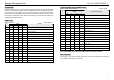
5. Music/Li-Po Cells:
The 4 LEDs have different meanings for ESC with or without a postfix letter of “HV”.
For ESC without a postfix letter of “HV”, for example, “Pentium-60A”, 4 LEDs
have 16 possible states, representing 16 rhythms for ESC. (Please read Table 1)
For ESC with a postfix letter of “HV”, for example, “Pentium-90A-HV”, 4 LEDs
represent the number of lithium battery cells (Please read Table 2)
WIRING SEQUENCE:
A) When you are using an ESC with a built-in BEC (Battery Elimination Circuit)
1. Disconnect the power pack from the ESC
2. Disconnect the BEC cable of the ESC (trio wires) from your receiver, then connect it
to the program card at the top right corner position marked with “BEC”
3. Connect the main power pack to the ESC
4. The LEDs on the program card will light, showing the current programmable value of
the ESC
Note: THE SEQUENCE OF STEP 2 AND STEP 3 CANNOT BE REVERSED! Otherwise
the program card cannot work properly.
B) When you are using an ESC without a built-in BEC
If the ESC is marked with “BEC OPTO”, that means this ESC hasn’t a built-in BEC, so you
must use an additional battery pack (4.8-6V) to power the program card, and usually a
receiver battery pack is a good choice.
1. Disconnect the power pack from the ESC
2. Disconnect the BEC cable of the ESC (trio wires) from your receiver, then connect it
to the program card at the top right corner position marked with “BEC”
3. Connect the receiver battery pack (4.8-6V) to the program card at the top right corner
position marked with “Batt.”
4. Connect the main power pack to the ESC
5. The LEDs on the program card will light, showing the current programmable value of
the ESC
NOTE: * THE SEQUENCE OF STEP 2 , STEP 3 AND STEP 4 CANNOT BE REVERSED!
Otherwise the program card cannot work properly.
NOTE: ** Don’t use a battery pack more than 6V to supply the program card!