
User Manual


Programming a Telemetry Event with a Switch
This example uses the THR switch to trigger the announcement of a telemetry value (signal
strength) and time.
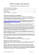
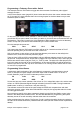
In the Custom Switch menu (page 8/13) shown below the left column has custom switches listed
as ‘S1’ though ‘SO’ simply because there is not enough space for the three letter acronym used
elsewhere (SW1 to SWO).
On this menu you find the custom switches. In the left column, among all the logical statements,
you will also find an option called Time. When you select it, you will be able to choose the OFF and
ON durations. This option is used in the Voice Switches to allow repetition of a voice or telemetry
event in a loop with a pre-set time interval defined by the custom switch SW2.
So in the example above we see:
SW1 Time Off 27 On 3 THR
This means that when the THR switch is on SW1 will be on for 3 seconds and then off for 27
seconds repeating every 30 seconds until THR is turned off.
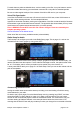
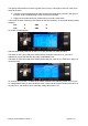
SW1 is the switch we are going to use to trigger the telemetry voice event on the safety/voice
switches menu, as shown in the last picture on page 3.
There we have VS22 and VS23 programmed to play two different telemetry events in a loop every
30 seconds. As explained above, we use SW1 to trigger both voice switches. One is set to play the
RSSI event and the other to play the Tim2 (i.e., Timer 2) value. The order of the files played in the
loop is the same as the order of the Voice Switches. In this case the RSSI info will be played first
and then the Timer 2 time, but only when THR switch is 'on' causing Custom Switch SW1 to come
'on' and 'off' as programmed.
Programming Voice Alarms.
A particularly useful application of the voice feature is programming a spoken alarm to sound
when, for example, the pack voltage or the RSSI drops under a certain value. To do this, in
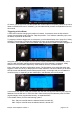
Custom Switches, page 9/13 of the model setup screens, we enter:
S5 v<ofs A1= 4.8v
S6 v<ofs RSSI 45
So here we have two custom switches. One will turn on if A1 voltage falls under 4.8v, and the other
will turn on if RSSI (Received Signal Strength Indication) is less than 45dBi. The logic statement
v<ofs means ‘a value (v)’ is less than a ‘set point value (s)’.
The software monitors the value of the pack voltage and RSSI and compares them with their
respective set point values. When either falls below the set point, the appropriate switch is turned
on and triggers the alarm.
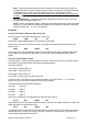
Now we have to specify which alarm message is played by using SW5 and SW6 to control voice
alarms in the Safety/Voice switches menu. This is a little different from programming the spoken
telemetry events as we will use safety switches rather than voice switches.
Safety switches have four options. The first two, S and X, perform the safety function by replacing
the value of the throttle stick with a predetermined safe value (see the manual Ersk9x Explained for
details).
Ersky9x Voice Explained: Version 1 page 5 of 12