
User Manual

The switches and LED assembly are mounted on the this board too, so that when you remove the
board they will be removed with it.
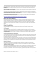
Hold the box lengthwise with both hands,
your thumbs on the top edges and fingers
pressing underneath the base of the box.
Push upwards with your fingers, bending
the base of the box upwards and hence
pushing the circuit board up. With enough
force the circuit board will spring out of the
detents at one end. Remove the box.
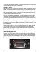
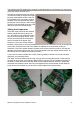
Adding the Components
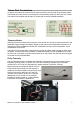
Orient the circuit board with the switches
toward yourself and the top away from
you. The board is now oriented the same
way as the circuit diagram above. There
are four pins at the top left of the board
and five sockets on the bottom right.
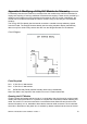
Solder the 2,700 Ohm resistor between
the base of the top left pin and the pad adjacent to the second socket from the top on the right side
of the board. Ensure that the end of the resistor is soldered as low as possible on the pin.
Solder the 4,700 Ohm resistor between the base of the second from the top left pin and the pad
adjacent to the bottom right socket. (Do not use the adjacent hole with copper trace around it, as
this terminal is not connected to the bottom socket.)
If you intend to use this module with a FrSky Taranis (possibly to enable use of older V8 series
receivers) you must fit the diode.
The “base” end of the diode is the one with a ring (in terms of the diode symbol, it's the end with
the thick bar at the point of the triangle). Bend back the wire from this end parallel to the body of
the diode. Cut the two wires so that the diode can be installed vertically, as shown. Spread the
wires apart and solder the short wire to the pad adjacent to the second lowest socket. Bend the
longer wire to fit and solder it to the end of the resistor adjacent the lowest socket.
9XR Pro: Introduction to the Hardware: version 1 11