
User Manual

Appendix A: Modifying a FrSky DJT Module for Telemetry
For telemetry data from the model to be conveyed from the module to the 9XR Pro transmitter for
display and sounding of warnings, additional connections are required. These can be provided by a
cable from the Futaba port on the transmitter to the socket on the DJT module. Alternatively, the
module can be modified to eliminate the need for a cable. Doing so will void your manufacturers
warranty.
The Turnigy 9XR Pro already has the internal connections needed to accept telemetry signals
from the module. The Ersky9x firmware already has the coding needed to display the telemetry
data not only from all the FrSky sensors but also from the Winged Shadow How Hi altimeter.
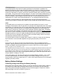
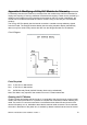
Circuit Diagram:
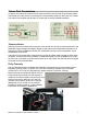
Parts Required
R43: 2,700 Ohm ½ Watt resistor
R44: 4,700 Ohm ½ Watt resistor
D3: BAT85 Schottky Diode (1N5819 Schottky diode may be substituted)
Note: The diode is only required if the module is for use in a Taranis transmitter.
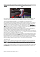
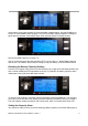
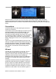
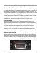
Opening the DJT Module
Undo the screws and release the back cover. It is connected to the circuit board by a short coaxial
cable to the base of the antenna. It is possible to complete the modifications without releasing this
cable. The small U.FL connector used at the circuit board end has limited life and should not be
removed frequently, so it is desirable to leave the the antenna cable connected. The circuit board,
which lies in the bottom of the plastic box, is retained by detents moulded into each end of the box.
9XR Pro: Introduction to the Hardware: version 1 10