
User Manual

© D Bird 2014 Page 3
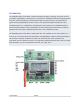
Initial Set-Up
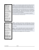
STEP-1 Mount the FC on the frame with the LCD facing front
and the buttons facing back. You can use the supplied anti-
static foam container as a form of protective case for the Flight
Controller on the craft.
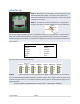
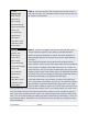
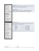
STEP-2 Connect the receiver outputs to the corresponding
left-hand side of the controller board. The pins are defined as:
Ensure the negative (black or brown) is orientated so that it is on the pin that is nearest to the
edge of the Flight Controller Board, so looking at the board the colour sequence will be Black,
Red and Orange. The channels are connected as follows from the front of the board towards the
push buttons: -
Receiver Channel
Flight Controller
Aileron
---
Aileron
Elevator
---
Elevator
Throttle
---
Throttle
Rudder
---
Rudder
AUX1
---
AUX
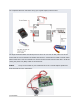
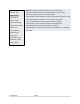
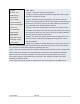
Typical receiver servo connections are:
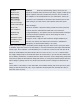
STEP-3 Connect the ESC’s to the right side of the Flight Controller Board. M1 is towards
the front of the board and M8 is nearest to the push buttons. The negative (black or brown) lead
towards the edge of the FC. The negative (black or brown) lead is connected to the edge of the
Flight Controller.
DO NOT MOUNT THE PROPELLERS AT THIS STAGE – FOR SAFETY REASONS