
User Manual

© D Bird 2014 Page 13
Gimbal Connection Guide
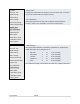
Enable the Camera Control by turning it on by going to "Cam Stab
Settings" screen and set the gains to a non-zero value. Start with 500.
A negative value reverses servo direction. Adjust value until camera is
steady.
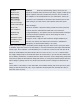
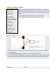
1. The Gimbal Roll servo is connected to Motor-7 output.
2. The Gimbal Pitch servo is connected to Motor-8 output.
Connection diagram:
3. Use the offset values to trim servo position, but keep the values close to 50% by adjusting
servo linkage first.
4. The camera stabilisation starts as soon as you move the Throttle any stick
5. If you put the Throttle at Idle/Minimum the camera stabilisation will be switched-OFF. NOTE:
If you are using an “OPTO” ESC you may need an external 5v power source from an SBEC.
PI Editor
Receiver Test
Mode Settings
Stick Scaling
Misc. Settings
Self-Level Settings
Camera Stab Settings
Sensor Test
ACC Calibration
CPPM Settings
Mixer Editor
Show Motor Layout
Load Motor Layout
Factory Reset