
Manual
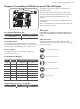
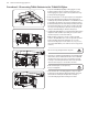
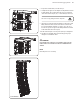
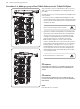
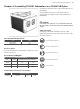
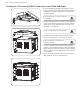
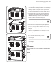
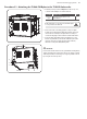
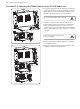
Table Of Contents
- Important Safety Instructions
- Legal Disclaimer
- Limited warranty
- Chapter 1: Safety Information
- Chapter 2: Introduction
- Chapter 3: Assembling a TLX84 Array on a TLX84-FLB Flybar
- Chapter 4: Assembling TLX215L Subwoofers on a TLX84-FLB Flybar
- Chapter 5: Assembling a TLX84 Array with a TLX215L Subwoofer
- Chapter 6: Groundstack of two TLX215L Subwoofers
- Chapter 7: Groundstack TLX215L Subwoofer and TLX84 Array
- Chapter 8: Safety Inspection
- Chapter 9: Enclosure quantities and combinations for TLX84-FLB flybar suspension at 10:1, 7:1, 5:1 design factors
- Manufacturer’s Declaration

TLX84 and TLX215L Rigging Manual 27
6. Prior to attaching the lower subwoofer, ensure that bottom mount hardware
on the upper subwoofer and upper mount hardware on the lower subwoofer
are in their stored positions. Carefully lower the ybar/subwoofer assembly
and physically align the top and bottom subwoofers so that front lower
mounting links (11) and the rear drop link (13) of the top subwoofer will
properly align with the mount link slots (14) and rear drop link channel (16)
of the lower subwoofer.
7. Pull out the lower subwoofer's front pins (15) then remove the front lower
rigging pins (10) of the top subwoofer. Allow front mounting links (11) to
slide downwards from the top subwoofer into the bottom subwoofer’s
mount link slots (14). Secure the mounting links to the upper subwoofer
with pins (10) and to the lower subwoofer with pins (15).
Take care not to trap your ngers between components.
8. Remove the rear pin (12) and the rear drop-down link (13) will drop down.
Check that the drop down link (13) and its pivot pin and circlip and are all
present, clean, and in good condition. Check that the circlip is correctly
holding the pivot pin in place, and preventing it and the drop down link from
falling out.
Align the top subwoofer's drop-down link (13) with the hole (16) in the lower
subwoofer's rear drop link channel. Insert the rear pin (12) to secure the
subwoofers together.
Double check all the connections to make sure that the
TLX215L subwoofers and the TLX84-FLB ybar are securely
connected together.
9. The addition of one more TLX215L subwoofer is performed by repeating
steps 7 through 8.
WARNING
DO NOT EXCEED A TOTAL QUANTITY OF 3 TLX215L SUBWOOFERS FOR ONE TLX84-
FLB FLYBAR. FAILURE TO FOLLOW INSTRUCTIONS MAY CAUSE PERMANENT INJURY
OR DEATH.
NOTE
Disassembly is the reverse of assembly.
9
12
13
16
10
11
14
15