
Manual
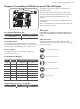
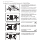
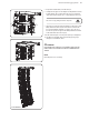
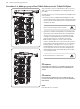
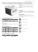
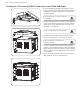
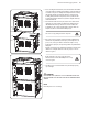
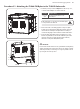
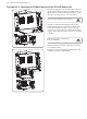
Table Of Contents
- Important Safety Instructions
- Legal Disclaimer
- Limited warranty
- Chapter 1: Safety Information
- Chapter 2: Introduction
- Chapter 3: Assembling a TLX84 Array on a TLX84-FLB Flybar
- Chapter 4: Assembling TLX215L Subwoofers on a TLX84-FLB Flybar
- Chapter 5: Assembling a TLX84 Array with a TLX215L Subwoofer
- Chapter 6: Groundstack of two TLX215L Subwoofers
- Chapter 7: Groundstack TLX215L Subwoofer and TLX84 Array
- Chapter 8: Safety Inspection
- Chapter 9: Enclosure quantities and combinations for TLX84-FLB flybar suspension at 10:1, 7:1, 5:1 design factors
- Manufacturer’s Declaration

24 TLX84 and TLX215L Rigging Manual
Procedure 3.2: Adding a group of four TLX84 Cabinets to the TLX84-FLB Flybar
Groups of four cabinets can be pre-assembled using Procedure 3.1, steps 8 to 11,
and then connected to the TLX84-FLB ybar as an assembled group of four just
prior to ying.
The TLX84 cabinets connect to each other using the front mounting links, and the
rear drop-down link.
1. Remove the top pins (12). Carefully lift the TLX84-FLB ybar on top of the
top TLX84 cabinet and align the ybar's front links (1) with the top mounting
slots (11) of the cabinet. Insert the front pins (12) to secure the front links (1)
of the ybar to the cabinet.
Take care not to trap your ngers between components.
2. Support the rear of the ybar and align the ybar's drop-down link (4) with
the desired hole (13) in the TLX84 rear bracket. The holes are marked with
the angle from 0 to 6 degrees. Choose the correct hole that corresponds
to the angle recommended by EASE FOCUS II software for the rst TLX84
cabinet. Insert the rear pin (5) to secure the link to the top cabinet.
Note: normally the 0 degree hole is selected to attach the top TLX84
enclosure to the TLX84-FLB in order to set the site angle of the top element
parallel to the ybar. This allows the TLX84-FLB to serve as a visual reference
for checking array focus on the audience area, i.e., if you can see the top
of the TLX84-FLB then you are outside the vertical coverage pattern of the
array. The angles of the other cabinets can be adjusted by supporting the
cabinet weight and moving the drop-down links (4) of the various cabinets
to the desired angle holes (13).
Double check that all pins are correctly inserted.
WARNING
DO NOT EXCEED A TOTAL QUANTITY OF 8 TLX84 CABINETS FOR ONE TLX84-FLB
FLYBAR. FAILURE TO FOLLOW INSTRUCTIONS MAY CAUSE PERMANENT INJURY
OR DEATH.
WARNING
DO NOT FLY THE PRE-ASSEMBLED GROUPS OF TLX84 CABINETS WITHOUT THE
TLX84-FLB FLYBAR. FAILURE TO FOLLOW INSTRUCTIONS MAY CAUSE PERMANENT
INJURY OR DEATH.
NOTE
Disassembly is the reverse of assembly.
13
1
12
11
4 5