
Manual
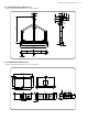
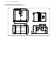
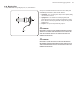
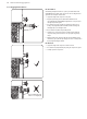
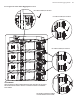
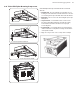
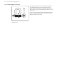
Table Of Contents
- Important Safety Instructions
- Legal Disclaimer
- Limited warranty
- Chapter 1: Safety Information
- Chapter 2: Introduction
- Chapter 3: Assembling a TLX84 Array on a TLX84-FLB Flybar
- Chapter 4: Assembling TLX215L Subwoofers on a TLX84-FLB Flybar
- Chapter 5: Assembling a TLX84 Array with a TLX215L Subwoofer
- Chapter 6: Groundstack of two TLX215L Subwoofers
- Chapter 7: Groundstack TLX215L Subwoofer and TLX84 Array
- Chapter 8: Safety Inspection
- Chapter 9: Enclosure quantities and combinations for TLX84-FLB flybar suspension at 10:1, 7:1, 5:1 design factors
- Manufacturer’s Declaration

18 TLX84 and TLX215L Rigging Manual
2.13 TLX84 Cabinet Mounting Components
The TLX84 cabinet has 2 mounting slots (2) at the top, 2 retractable mounting
lugs (3) at the bottom, a choice of 7 mounting holes (6) at the rear top, and a
drop-down link (8) at the rear bottom. These allow the TLX84 cabinets to be
connected together, attached to the TLX84-FLB ybar, and TLX215L subwoofer.
1. Front Pins – These are used to secure the bottom links (3) of the TLX84
cabinet or TLX215L subwoofer above, or to the bottom mounting links of the
TLX84-FLB ybar. They are attached with lanyards to prevent loss.
2. Top Mounting Slots – These accept the bottom links (3) of the TLX84
cabinet or TLX215L subwoofer above, or the bottom mounting links of the
TLX84-FLB ybar.
3. Bottom Mounting Links – These retractable links t into and connect
to the top mounting slots (2) of the TLX84 cabinet or TLX215L subwoofer
below.
4. Bottom Pins – These pins are used to secure the bottom mounting links (3)
in the up or down position. They have lanyards attached.
5. Bottom Bolts – These bolts are used to secure the bottom mounting links
(3) in their slots so they move up or down.
6. Rear Mounting Holes – These are used to connect the rear drop-down
link (8) of the TLX84 cabinet or TLX215L above, or the drop-down link of the
TLX84-FLB ybar. The angle of the cabinet is dened by choosing one of
these 7 holes.
7. Rear Pin – This is used to secure the rear drop-down link (8) of the TLX84
cabinet or TLX215L subwoofer above, or the drop-down link of the TLX84-
FLB ybar, to the selected rear mounting hole (6). If the drop-down link (8) is
not in use, then the pin is used to secure it.
8. Drop-Down Link – This connects to the rear mounting hole (6) of the
TLX84 cabinet or TLX215L subwoofer (for ground stacking) below it.
9. Circlip – This holds the pivot pin (9) in place, and prevents the pivot pin and
the drop down link (8) from falling out.
10. Pivot Pin – This pin holds the drop-down link (8) in place and allows it to
rotate in the up or down position. A circlip (9) holds the pivot pin in place.
Degrees
0
2
4
6
1
3
5
7
6
8
8
9
10