
Manual
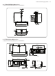
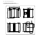
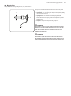
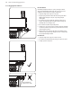
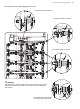
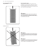
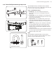
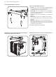
Table Of Contents
- Important Safety Instructions
- Legal Disclaimer
- Limited warranty
- Chapter 1: Safety Information
- Chapter 2: Introduction
- Chapter 3: Assembling a TLX43 Array on a TLX43-FLB Flybar
- Chapter 4: Assembling one TLX212L Subwoofer on a TLX43-FLB Flybar
- Chapter 5: Assembling a TLX43 Array with a TLX212L Subwoofer
- Chapter 6: Groundstack of two TLX212L Subwoofers
- Chapter 7: Groundstack TLX212L Subwoofer and TLX43 Array
- Chapter 8: Safety Inspection
- Chapter 9: Enclosure Quantities and Combinations for TLX43-FLB Flybar Suspension at 10:1, 7:1, 5:1 Design Factors
- Manufacturer’s Declaration

18 TLX43 and TLX212L Rigging Manual
2.13 TLX43 Cabinet Mounting Components
The TLX43 cabinet has two xed mounting lugs (2) at the top, two xed
mounting lugs (3) at the bottom, a choice of four mounting holes (4) at the rear
top, and a drop-down link (6) at the rear bottom. These allow the TLX43 cabinets
to be connected together, and attached to the TLX43-FLB ybar.
1. Front Pins – These are used to secure the top mounting lugs (2) of the
TLX43 cabinet to the bottom lugs (3) of the TLX43 cabinet above, or to the
bottom mounting lugs of the TLX43-FLB ybar. They are attached with
lanyards to prevent loss.
2. Top Mounting Lugs – These connect to the bottom lugs (3) of the TLX43
cabinet above, or to the bottom mounting lugs of the TLX43-FLB ybar.
3. Bottom Mounting Lugs – These connect to the top lugs (2) of the TLX43
cabinet below.
4. Rear Mounting Holes – These are used to connect the rear drop-down
link (6) of the TLX43 cabinet above, or the drop-down link of the TLX43-FLB
ybar. The angle of the cabinet is dened by choosing one of these four
holes. They are marked as follows, starting with the top hole: 0 , 2.5, 5.0, and
7.5 degrees.
5. Rear Pin – This is used to secure the rear drop-down link (6) of the TLX43
cabinet above, or the drop-down link of the TLX43-FLB ybar, to the selected
rear mounting hole (4). If the drop-down link (6) is not in use, then the pin is
used to secure it using the bottom mounting hole (7.5 degrees).
6. Drop-Down Link – This connects to the rear mounting hole (4) of the TLX43
cabinet below it.
7. Circlip – A circlip (7) holds the pivot pin (8) in place, and prevents the pivot
pin and the drop down link (6) from falling out.
8. Pivot Pin – This pin holds the drop-down link (6) in place and allows it to
rotate in the up or down position. A circlip (7) holds the pivot pin in place.
21
12
3
3
Degrees
0
2.5
5.0
7.5
54
6
Degrees
0
2.5
5.0
7.5
7
8
6