TLX LIVERPOOL SERIES TLX212L Compact Dual 12" Subwoofer for Portable and Fixed Installation Applications TLX43 Compact Dual 2 Way 4" Line Array Element for Portable and Fixed Installation Applications TLX43-FLB Fly Bar for TLX43 and TLX212L for Suspended or Ground Stacked Arrays Rigging Manual !! WARNING! This rigging manual contains important safety information, and it must be kept in a safe place for future reference.
TLX43 and TLX212L Rigging Manual Table of Contents Important Safety Instructions....................................... 3 Legal Disclaimer.............................................................. 3 Limited warranty............................................................. 3 Chapter 1: Safety Information....................................... 4 Chapter 2: Introduction.................................................. 6 Chapter 3: Assembling a TLX43 Array on a TLX43-FLB Flybar....................
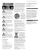
TLX43 and TLX212L Rigging Manual Important Safety Instructions Terminals marked with this symbol carry electrical current of sufficient magnitude to constitute risk of electric shock. Use only high-quality professional speaker cables with ¼" TS or twist-locking plugs pre-installed. All other installation or modification should be performed only by qualified personnel.
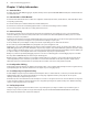
TLX43 and TLX212L Rigging Manual Chapter 1: Safety Information 1.1 Intended Use The rigging components (TLX43-FLB flybar, rigging pins, drop links) shall only be used in conjunction with TURBOSOUND TLX43 loudspeakers and TLX212L subwoofers as described in this manual. 1.2 Intended Use of this Manual The instructions in this manual describe how to assemble various configurations of TLX43 loudspeaker cabinets, TLX212L subwoofers, and the TLX43-FLB, in readiness for suspending or ground stacking.
TLX43 and TLX212L Rigging Manual 5 1.7 Secondary Safeties All loudspeakers flown in theatres, studios or other places of work and entertainment must, in addition to the principle load bearing means of suspension, be provided with an independent, properly rated, and securely attached secondary safety. Only steel wire ropes or steel chains of an approved construction and load rating shall be used as secondary safeties. Plastic-covered steel wire ropes are not permitted for use as secondary safeties.
TLX43 and TLX212L Rigging Manual Chapter 2: Introduction 2.
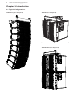
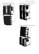
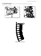
TLX43 and TLX212L Rigging Manual TLX212L and TLX43 Array (See Chapter 5) Two TLX212L Subwoofer Groundstack (See Chapter 6) TLX212L and TLX43 Array Groundstack (See Chapter 7) 7
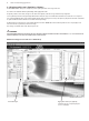
TLX43 and TLX212L Rigging Manual 2.2 Rigging and Acoustic Simulation Software The EASE FOCUS II software allows you to configure the system for optimal performance and coverage in the venue. The software can be downloaded from http://www.afmg.eu/index.php/products.html The quantity of cabinets can be varied, the angles of each cabinet can be adjusted, and the SPL coverage calculated for any configuration.
TLX43 and TLX212L Rigging Manual 2.3 TLX43 Cabinet Angles The angle of each TLX43 cabinet relative to the cabinet above it, is varied by selecting one of four mounting holes in the rear mounting bracket. These are labeled 0, 2.5, 5.0, and 7.5 degrees. Degrees 0 2.5 5.0 7.
TLX43 and TLX212L Rigging Manual 2.4 Weights Item TLX43 Quantity 1 2 3 4 5 6 7 8 9 10 Weight (kg) 8 16 24 32 40 48 56 64 72 80 Weight (lbs) 17.6 35.3 52.9 70.6 88.2 106 123 141 159 176 Item TLX212L Quantity 1 2 Weight (kg) 43 86 Weight (lbs) 94.8 190 Item TLX43-FLB Quantity 1 2 Weight (kg) 6.8 13.6 Weight (lbs) 15 30 2.5 TLX43-FLB Flybar Working Load Limit (WLL) Item TLX43-FLB WLL (kg) 94 134 188 WLL (lbs) 207 296 414 Design Factor 10:1 7:1 5:1 2.
TLX43 and TLX212L Rigging Manual 2.7 TLX43-FLB Flybar Dimensions See Chapter 8 for information regarding inspection, care, and maintenance. 12 [0.5] 22 [0.9] 23.3 [0.9] 450 [17.7] 66 [2.6] 198 [7.8] ] [Ø0.8 132 [5.2] 264 [10.4] 475.5 [18.7] Ø20 CL 534 [21] 102 [4] SIDE 588 [23.1] TOP 501 [19.7] 9 [0.4] CL 450 [17.7] 9 [0.4] FRONT 2.8 TLX43 Cabinet Dimensions See Chapter 8 for information regarding inspection, care, and maintenance. CL 388 [15.3] 290 [11.4] 12 [0.5] CL 84 [3.
TLX43 and TLX212L Rigging Manual 2.9 TLX212L Subwoofer Dimensions See Chapter 8 for information regarding inspection, care, and maintenance. 576 [22.7] 12 [0.5] 511 [20.1] 542 [21.3] 518 [20.4] 448 [17.6] 547 [21.5] 482 [19] 488 [19.2] 205 [8.1] 175 [6.9] 29 [1.2] BACK TOP CL FRONT SIDE 182 [7.
TLX43 and TLX212L Rigging Manual 13 2.10 Rigging Pins See Chapter 8 for information regarding inspection, care, and maintenance. 1 2 1 3 These pins are the fundamental mechanical fastener for the assembly of the TLX43-FLB flybar, TLX43 cabinet, and the TLX212L subwoofer. 1. Spring Balls – These are locking devices that prevent the pin from pulling out once it has been inserted. 2.
TLX43 and TLX212L Rigging Manual 2.10.1 Rigging Pin Installation 2 1 Pin Installation The following example shows how to use a pin to join the lugs of a TLX43 cabinet and a TLX43-FLB flybar. Exact details of the connections for various configurations are given in the various chapters of this manual. 1. Support the weight of the components to be joined. 2. Align the top lug of the TLX43 cabinet with the bottom lug of the TLX43FLB flybar.
TLX43 and TLX212L Rigging Manual 2.10.2 Typical Locations where Rigging Pins are used PINS CORRECTLY INSERTED, ALL THE WAY IN PINS CORRECTLY INSERTED, ALL THE WAY IN PINS CORRECTLY INSERTED, ALL THE WAY IN !!WARNING VERIFY THAT EACH PIN IS CORRECTLY INSERTED, AND THAT EACH PIN CANNOT BE PULLED OUT WITHOUT PRESSING THE RELEASE BUTTON FIRST. FAILURE TO FOLLOW INSTRUCTIONS MAY CAUSE PERMANENT INJURY OR DEATH.
TLX43 and TLX212L Rigging Manual 2.11 Vertical Orientation CORRECT INSTALLATION Vertical Orientation Only! The mechanical design of the TLX43 cabinet, TLX212L subwoofer, and the TLX43-FLB flybar uses lugs, links, and pins to assemble the various components. The mechanical strength comes from the cabinet's metal side pieces and the pins, and not through the wooden cabinets. The cabinets are supported vertically below each other, and vertically below the flybar.
TLX43 and TLX212L Rigging Manual 2.12 TLX212L Subwoofer Mounting Components The TLX212L subwoofer has two retractable mounting links at the bottom (6), one mounting hole at the rear top (9), and a drop-down link (8) at the rear bottom. The TLX43-FLB flybar is supplied with two drop down links that fit in two locations (1) on top of the subwoofer. These mounting points allow the subwoofer to be connected to the TLX43-FLB flybar in various configurations, or joined to another TLX212L.
TLX43 and TLX212L Rigging Manual 2.13 TLX43 Cabinet Mounting Components 1 The TLX43 cabinet has two fixed mounting lugs (2) at the top, two fixed mounting lugs (3) at the bottom, a choice of four mounting holes (4) at the rear top, and a drop-down link (6) at the rear bottom. These allow the TLX43 cabinets to be connected together, and attached to the TLX43-FLB flybar. 2 2 1 1.
TLX43 and TLX212L Rigging Manual 19 2.14 TLX43-FLB Flybar Mounting Components The TLX43-FLB flybar shall only be used with TLX43 cabinets and TLX212L subwoofers. One side is used to connect to a TLX43 cabinet, the other side is used to connect to the top (or bottom) of a TLX212L subwoofer. 3 1 1 2 2.14.1 Use with TLX43 Cabinet 1. Mounting Lugs – These connect the flybar to the top lugs of the TLX43 cabinet. The connections are secured using the front pins of the TLX43 cabinet. 2.
TLX43 and TLX212L Rigging Manual 2.14.1 TLX43-FLB Flybar (continued) 6 1 5 2 4 2 1 3 2.14.2 Use with TLX212L Subwoofer 1. Front Pins* – These secure the mounting lugs (2) of the flybar either to the mounting links (3) that fit into the top of the TLX212L subwoofer, or to the retractable links at the bottom of the TLX212L subwoofer. 2.
TLX43 and TLX212L Rigging Manual 21 Chapter 3: Assembling a TLX43 Array on a TLX43-FLB Flybar The following procedure shows how to build an array of TLX43 cabinets by adding them one at a time. Alternatively, cabinets can be pre-assembled into groups of four, and then connected to the flybar at a later time. This method is shown in procedure 3.2. The system is suspended using a TLX43-FLB flybar that attaches to your lifting system.
TLX43 and TLX212L Rigging Manual Procedure 3.1 Connecting TLX43 Cabinets to the TLX43-FLB Flybar 1. The TLX43-FLB flybar comes with extra components (marked* in this drawing) that are only used when rigging the TLX212L subwoofer. Remove these components from the flybar and keep them together in a safe place. * * 1 2 2 1 3 4 2. Prepare the first TLX43 cabinet, by pulling out the front two pins (1) from the top mounting lugs (2), and remove the rear pin (4) from the rear mounting holes (3).
TLX43 and TLX212L Rigging Manual 7 4 3 23 5. Align the flybar's drop-down link (7) with the desired hole (3) in the TLX43 rear bracket. The holes are marked with the angle. Choose the correct hole that corresponds to the angle recommended by EASE FOCUS II software for the first TLX43 cabinet. Insert the rear pin (4). Note: normally the 0 degree hole is selected to attach the top TLX43 enclosure to the TLX43-FLB in order to set the site angle of the top element parallel to the flybar.
TLX43 and TLX212L Rigging Manual Procedure 3.1 continued 9. Insert the front two pins (1), to secure the front top mounting lugs (2) of this TLX43 cabinet to the two bottom mounting lugs (8) of the TLX43 cabinet above it. !!CAUTION: 1 1 Support the rear of the cabinet until the rear drop-down link (5) is connected (next step). Take care not to trap your fingers between components. 10.
TLX43 and TLX212L Rigging Manual 25 Procedure 3.2: Adding a group of four TLX43 Cabinets to the TLX43-FLB Flybar 3 4 4 3 Groups of four cabinets can be pre-assembled using Procedure 3.1, steps 7 through 10, and then connected to the TLX43-FLB flybar as an assembled group of four just prior to flying. 6 The TLX43 cabinets connect to each other using the top and bottom front mounting links, and the rear drop-down link. 1.
TLX43 and TLX212L Rigging Manual Procedure 3.2 continued 3. Insert the front two pins (3) to secure the front mounting lugs of the flybar (8) with the two top mounting lugs (4) of the TLX43 cabinet. 3 !!CAUTION: Do not let the TLX43 cabinet assembly hang from the two front lugs only. This may cause damage to the front lugs. Always support the weight of the cabinets until the rear drop-down link (9) is secured with its pin (6) in the next step. 4.
TLX43 and TLX212L Rigging Manual 27 Chapter 4: Assembling one TLX212L Subwoofer on a TLX43-FLB Flybar The following procedure describes how to assemble a single TLX212L subwoofer to the TLX43-FLB flybar. The TLX43-FLB flybar is attached to the top of the TLX212L subwoofer, using 2 front pins, 2 mounting links, and a rear drop-down link, supplied with the TLX43-FLB flybar. !!WARNING DO NOT EXCEED A TOTAL QUANTITY OF 2 TLX212L SUBWOOFERS FOR ONE TLX43-FLB FLYBAR.
TLX43 and TLX212L Rigging Manual Procedure 4.1 - Installing the TLX212L Subwoofer Top Mounting Links The TLX43-FLB flybar is supplied with two sub links (1) that are installed in the top of the TLX212L subwoofer. These form the mounting points for connecting the flybar to the subwoofer. 1. Remove the upper-front pin (3) of the subwoofer. 2. Lower the mounting link (1) into the slot on top of the subwoofer, until the middle hole of the link lines up with the hole of the pin (3). 3.
TLX43 and TLX212L Rigging Manual 29 Procedure 4.2 - Preparing the TLX43-FLB Flybar for a TLX212L Subwoofer The TLX43-FLB flybar is supplied with captive front pins and a removable rear sub drop link and rigging pin assembly that is only used when suspending the TLX212L subwoofer. 1. Remove the two front pins (4) from the front mounting lugs (5). 2. Remove the lowest pin (6) from the rear drop-down link (7) as shown. Procedure 4.3 - Attaching the TLX43-FLB Flybar to the TLX212L Subwoofer 1.
TLX43 and TLX212L Rigging Manual Procedure 4.3 continued 4. Line up the hole in the rear drop-down link (7) of the flybar, with the hole in the rear mounting bracket of the subwoofer. Insert the rear pin (6) to capture the drop-down link. Double check all pins are correctly inserted, and that the flybar is now securely attached to the subwoofer at all points. NOTE Disassembly is the reverse of assembly.
TLX43 and TLX212L Rigging Manual Procedure 4.4 - Connecting a Second TLX212L Subwoofer 1. Attach a bow shackle or other lifting equipment securely to the correct flybar pick point hole as recommended by EASE FOCUS II software, then attach the hook and chain to the bow shackle. 2. Carefully raise the flybar/subwoofer to provide sufficient clearance for adding a second subwoofer, in preparation for the next steps. 3. Move the bottom TLX212L subwoofer to a position directly below the top subwoofer.
TLX43 and TLX212L Rigging Manual 7. Check that left and right front rigging pins (4) are correctly inserted - 4x rigging pins total. Check that the rear drop down link rigging pin (5) is correctly inserted. Double check all the connections to make sure that the TLX212L subwoofers and the TLX43-FLB flybar are securely connected together. NOTE Disassembly is the reverse of assembly. !!WARNING 4 5 DO NOT EXCEED A TOTAL QUANTITY OF 2 TLX212L SUBWOOFERS FOR ONE TLX43-FLB FLYBAR.
TLX43 and TLX212L Rigging Manual 33 Chapter 5: Assembling a TLX43 Array with a TLX212L Subwoofer The following procedure describes how to assemble a mixed array consisting of one TLX212L subwoofer and four TLX43 cabinets below it. One TLX43-FLB flybar is attached to the top of the TLX212L subwoofer, using components supplied with the TLX43-FLB flybar.
TLX43 and TLX212L Rigging Manual Procedure 5.1 - Attaching the top TLX43-FLB flybar to the TLX212L Subwoofer 1. Perform the previous procedures in Chapter 4: 4.1, 4.2, and 4.3, to attach the TLX43-FLB flybar to the TLX212L subwoofer. Procedure 4.1 4.2 4.3 Description of Work Check Installing the TLX212L Subwoofer Top Mounting Links Preparing the TLX43-FLB Flybar for suspending a TLX212L Attaching the TLX43-FLB Flybar to the TLX212L Subwoofer 2.
TLX43 and TLX212L Rigging Manual 35 Procedure 5.2 - Attaching the bottom TLX43-FLB Flybar to the TLX212L Subwoofer 1 2 1 1. Remove the two front pins (1) and the rear drop link and pins (2) from the second (bottom) flybar. (The rear drop link and pins are not used, but the two front pins are.) 2. Line up the flybar with the bottom of the TLX212L subwoofer as shown. 3.
TLX43 and TLX212L Rigging Manual 4. Support the rear of the flybar and align the rear hole (5) of the flybar with the lower hole in the rear drop-down link (4) of the subwoofer. 5. Insert the rear pin (6) to secure the drop-down link to the flybar. 4 5 6 Double check that all pins are correctly inserted, and that the lower flybar is now securely attached to the subwoofer. NOTE Disassembly is the reverse of assembly.
TLX43 and TLX212L Rigging Manual 37 Procedure 5.3 - Attaching the TLX43 Cabinets to the TLX43-FLB Flybar 1. Perform the previous procedures shown in Chapter 3 to attach a maximum of four TLX43 cabinets to the bottom TLX43-FLB flybar. Follow all safety precautions in the procedure. Procedure 3.1 Description of Work Check Connecting TLX43 cabinets to the TLX43-FLB flybar Alternatively, a previously-assembled group of four TLX43 cabinets can be assembled to the bottom TLX43-FLB flybar.
TLX43 and TLX212L Rigging Manual Chapter 6: Groundstack of two TLX212L Subwoofers The following procedure describes how to assemble a groundstack with two TLX212L subwoofers. The TLX212L subwoofers are attached using the 2 bottom mounting links and the rear drop-down link of the top subwoofer. !!WARNING DO NOT EXCEED A TOTAL QUANTITY OF 3 TLX212L SUBWOOFERS FOR THIS GROUNDSTACK CONFIGURATION. FAILURE TO FOLLOW INSTRUCTIONS MAY CAUSE PERMANENT INJURY OR DEATH.
TLX43 and TLX212L Rigging Manual 39 Procedure 6.1 - Assembling the two TLX212L Subwoofers 1. Make sure the bottom subwoofer is on a flat, horizontal, and steady surface. 2. Carefully lower the top subwoofer on top of the bottom subwoofer and allow the stacking runners on the bottom of the upper enclosure to self-center with the stacking recesses on the top of the lower enclosure. Take care not to trap your fingers between components. 3.
TLX43 and TLX212L Rigging Manual Chapter 7: Groundstack TLX212L Subwoofer and TLX43 Array The following procedure describes how to assemble a groundstack with a TLX212L subwoofer as a base and an array of four TLX43 cabinets on top. The TLX43-FLB flybar is attached to the top of the TLX212L subwoofer, using 2 front pins and a rear drop-down link supplied with the TLX43-FLB flybar. The array of up to 4 TLX43 cabinets is built on top of the TLX43-FLB flybar.
TLX43 and TLX212L Rigging Manual 41 Procedure 7.1 - Attaching the top TLX43-FLB Flybar to the TLX212L Subwoofer 1. Perform the previous procedures in Chapter 4: 4.1, 4.2, and 4.3, to attach the TLX43-FLB flybar to the TLX212L subwoofer. Procedure 4.1 4.2 4.3 Description of Work Installing the TLX212L Subwoofer Top Mounting Links Preparing the TLX43-FLB Flybar for flying a TLX212L Attaching the TLX43-FLB Flybar to the TLX212L Subwoofer 2.
TLX43 and TLX212L Rigging Manual Procedure 7.2 - Attaching the TLX43 Cabinets to the TLX43-FLB Flybar 1. Prepare the first TLX43 cabinet, by pulling out the front two pins (3) from the top mounting lugs (4), and remove the rear pin (6) from the rear mounting hole (5). The rear drop-down link (7) of the cabinet will drop down. 2. Turn the TLX43 cabinet upside-down. 3.
TLX43 and TLX212L Rigging Manual 43 5. Align the flybar's link (9) with the desired hole (5) in the TLX43 rear bracket. The holes are marked with the angle. 6. Insert the rear pin (6) to secure the flybar link (9) to the TLX43 cabinet. Double check all pins are correctly inserted, before proceeding further. 7. Prepare the second TLX43 cabinet, by pulling out the front two pins (3) from the top mounting lugs (4), and remove the rear pin (6) from the rear mounting hole (5).
TLX43 and TLX212L Rigging Manual Procedure 7.2 continued 10. Insert the front two pins (3) to secure the front two mounting lugs to the two mounting lugs of the TLX43 cabinet below it. Support the rear of the cabinet until the rear link is connected in the next step. 3 3 Take care not to trap your fingers between components. 11. Align the rear link (7) of the bottom TLX43 cabinet with the desired mounting hole (5) in the rear of the TLX43 cabinet above it. 12.
TLX43 and TLX212L Rigging Manual 45 13. The addition of other TLX43 cabinets is performed by repeating procedure steps 7 through 12 for each additional cabinet. !!WARNING DO NOT EXCEED A TOTAL QUANTITY OF 4 TLX43 CABINETS FOR THIS GROUNDSTACK CONFIGURATION. FAILURE TO FOLLOW INSTRUCTIONS MAY CAUSE PERMANENT INJURY OR DEATH. NOTE Disassembly is the reverse of assembly.
TLX43 and TLX212L Rigging Manual Chapter 8: Safety Inspection !!The following notes must be read and followed before suspending the systems or ground stacking: Cabinets Inspect all cabinets carefully and make sure that all surfaces are clean, in good condition, and free from cracks, corrosion, or any other defects that may weaken the assembly. Check for any missing screws, rigging pins, mounting links, or drop down links, pivot pins, or their circlips.
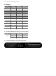
TLX43 and TLX212L Rigging Manual 47 Chapter 9: Enclosure Quantities and Combinations for TLX43-FLB Flybar Suspension at 10:1, 7:1, 5:1 Design Factors Maximum allowed TLX43 and TLX212L enclosure quantities and combinations for suspension using TLX43-FLB Fly Bar at 10:1, 7:1 and 5:1 design factors.
TLX43 and TLX212L Rigging Manual Manufacturer’s Declaration We, MUSIC Group Manufacturing PH Ltd. MUSIC Group Manufacturing PH Ltd. 17A Brunswick Street Hamilton HM 10 Bermuda Do hereby declare that the following components: TLX43 Loudspeaker Cabinets TLX212L Subwoofer Cabinets TLX43-FLB Flybar are in compliance with the relevant fundamental safety and health criteria of the applicable EC Directive(s). This declaration is void if unauthorised modifications are made to the equipment.
TLX43 and TLX212L Rigging Manual 49
TLX43 and TLX212L Rigging Manual
TLX43 and TLX212L Rigging Manual 51