
User's Manual


10 MANCHESTER Series Quick Start Guide 11
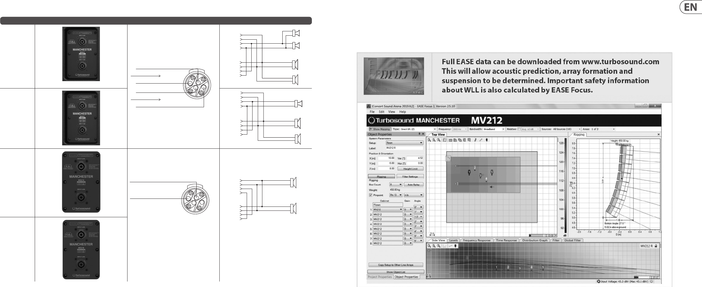
Connections
Mode Back Panel Connector Internal Schematic
MV212
BI-AMP, Input Low +
BI-AMP, Input Low -
BI-AMP, Input High +
BI-AMP, Input High -
1-
2-
2+
1+
Amplier Channel 1
Amplier Channel 2
LF 2
MHF 2
1+
+
-
+
-
+
-
1-
2+
2-
1+
1-
2+
2-
MHF 1
+
-
LF 1
NL4
Input/
Link
NL4
Input/
Link
MV212-XV
LF 2
MHF
1+
+
-
+
-
+
-
1-
2+
2-
1+
1-
2+
2-
LF 1
NL4
Input/
Link
NL4
Input/
Link
MS215
1-
2-
2+
1+
Input SUB -
Input SUB +
(MS215 and MS218 Front inputs do not use Pins 2+/2-)
LF 1
NL4
Input/
Link
1+
1-
2+
2 -
+
-
+
-
1+
1-
2+
2 -
NL4
Input/
Link
LF 2
MS218
Rigging and Acoustic Simulation Software
Refer to the MAN-FG rigging manual for safe suspension and installation of the loudspeakers, y grid and all suspension hardware.
MANCHESTER Series loudspeakers and y grid are designed and tested to strict BGV-C1 standards. Suspension of these speakers must be performed in accordance
with the rigging manual supplied with the MAN-FG y grid and available online at turbosound.com