LMS-A6 LOUDSPEAKER MANAGEMENT SYSTEM USER’S MANUAL Turbosound Ltd. Star Road, Partridge Green West Sussex RH13 8RY England Tel: +44 (0)1403 711447 Fax: +44 (0)1403 710155 web: www.turbosound.
user manual LMS-A6 CONTENTS Important Safety Information ................................................................................................................. 3 Thanks...................................................................................................................................................... 4 Unpacking the LMS-A6 ........................................................................................................................... 4 Introduction ...................
user manual LMS-A6 An example of this equipment has been tested and found to comply with the following European and international Standards for Electromagnetic Compatibility and Electrical Safety: Radiated Emissions (EU): EN55013-1 (1996) RF Immunity (EU): EN55103-2 (1996) RF Immunity, ESD, Burst Transient, Surge, Dips &Dwels Electrical Safety (EU): EN60065 (1993) IMPORTANT SAFETY INFORMATION Do not remove Covers.
user manual LMS-A6 THANKS Thank you for choosing the TURBOSOUND LMS-A6 for your application. Please spare a little time to digest the contents of this manual, so that you obtain the best possible performance from this unit. All TURBOSOUND products are carefully engineered for world class performance and reliability. If you would like further information about this or any other TURBOSOUND product, please contact us. We look forward to helping you in the near future.
user manual LMS-A6 INTRODUCTION The LMS-A6 is a versatile two input, six output, analogue loudspeaker management system in a 1U rack mount package that is designed for maximum sonic performance. It combines crossover and limiter functions and is uniquely configurable to custom requirements. The LMS-A6 can be configured for the following modes of operation: stereo 3-way, stereo 2-way, mono 4-way, plus mono 2-way.
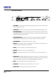
user manual LMS-A6 FRONT PANEL FUNCTIONS 24 5 7 11 12 8 POL 13 1. 6 9 10 13 Mono Band 1 – sums the Left and Right Band signals together (up position) and feeds them in mono to both Band 1 outputs. 2. Limiter cancel – disables all limiter functions and causes the LIMITER CANCEL LED to light. 3.
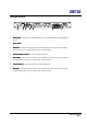
user manual LMS-A6 REAR PANEL FUNCTIONS AC 50/60Hz 40VA S.No 10 - 1001 - A 230V ALWAYS USE SAFETY GROUND NO USER SERVICEABLE PARTS INSIDE 1 1. 2 3 4 5 6 7 Mains Power - Connected via a standard IEC socket. A compatible power cord is supplied with the unit. 2. Power Switch. Switch 3. Mains Fuse - Located in a finger-proof fuseholder adjacent to the mains inlet. Always replace this fuse with the correct type as shown on the rear panel legend. 4.
user manual LMS-A6 SETTING UP AND OPERATING THE LMS-A6 This section describes the steps and checks to be taken when setting up the unit for the first time, and the operation of all the controls and indicators. Some of the custom operating parameters will have been set internally when unit left the factory. These are described in this section and you must check that these are appropriate for your system.
user manual LMS-A6 Connecting inputs and outputs This section describes how to connect signals to the LMS-A6 loudspeaker management system. The signal inputs are industry standard female XLR connectors and are wired as follows:Pin 1 = GROUND or COMMON Pin 2 = HOT or (+) or In-phase Pin 3 = COLD or (-) or Out of phase The electronically balanced inputs will take a maximum level of +20dBu at 10k ohm impedance. They will accept either balanced or unbalanced signals.
user manual LMS-A6 Power On Standby Mode When power is first switched on the LMS-A6 enters STANDBY mode. In this mode all outputs are muted to suppress any noise or transients while the circuitry settles down. The POWER STDBY switch determines how the unit will behave after power is applied.: Switch down: The unit will stay in standby mode. All outputs will stay muted and the red STANDBY MUTE LED will light.
user manual LMS-A6 When this switch is up (on) the Left and Right Band 1 signals are summed together and fed in mono to both Band 1 outputs. When the switch is down the Left and Right Band 1 signals remain independent from each other. Level Trims Band 1 and Band 3 have independent gain trims for fine adjustment of the system frequency response. If the internal preset band gains have been specified correctly these controls will nominally all be set central at 0dB.
user manual LMS-A6 restrict the full undistorted output of the amplifiers. Note that the actual output power available often depends on the mains supply voltage, which may ‘sag’ during heavy performances. In a system where the amplifiers are capable of exceeding the ratings of the speakers, set the threshold to a level appropriate to the speakers and NOT the clipping point of the amplifier.
user manual LMS-A6 TECHNICAL SPECIFICATIONS Inputs Two electronically balanced Impedance > 10k ohms CMRR >65dB 50Hz - 10kHz Outputs Six electronically balanced Source Imp < 60ohms Min. Load 600ohms Max. Level +20dBm into 600 ohm load Frequency Response ±0.5dB 20Hz - 20kHz Dynamic Range >110dB 20Hz -20kHz. Unwtd Distortion < 0.02% @ 1kHz, +18dBm Maximum Delay 650 mS. (Increment 2..
user manual LMS-A6 WARRANTY This product is warranted against defects in components and workmanship only, for a period of one year from the date of shipment to the end user. During the warranty period, TURBOSOUND will, at its discretion, either repair or replace products which prove to be defective, provided that the product is returned, shipping prepaid, to an authorised TURBOSOUND service facility.
Turbosound Ltd Star Road, Partridge Green West Sussex RH13 8RY England Tel:+44 (0)1403 711447 Fax: +44 (0)1403 710155 web: www.turbosound.