ASPECT TA-880 SYSTEM USER MANUAL Turbosound Ltd. Star Road, Partridge Green West Sussex RH13 8RY England Tel: +44 (0)1403 711447 Fax: +44 (0)1403 710155 web: www.turbosound.com Issue 1.
user manual TA-880 Contents EC Declaration of Conformity........................................................................................................................ 6 Introduction .................................................................................................................................................... 7 Turbosound Aspect System Concepts ..................................................................................................... 7 The Aspect Polyhorn™ Concept.
user manual TA-880 Horizontal Coverage................................................................................................................................ 25 Vertical Coverage .................................................................................................................................... 26 Wide and Narrow Flybar settings........................................................................................................... 26 Two-wide trapezoidal flybar FB-880/2W ......
user manual TA-880 Features ................................................................................................................................................... 49 Front Panel Functions ............................................................................................................................. 50 Rear Panel Functions...............................................................................................................................
user manual TA-880 General Features & Facilities .................................................................................................................. 75 Front Panel Functions T-25 ..................................................................................................................... 76 Front Panel Functions T-45 ..................................................................................................................... 77 Mechanical Installation .......................
user manual TA-880 EC DECLARATION OF CONFORMITY Manufacturer Turbosound Ltd Star Road, Partridge Green, West Sussex, RH13 8RY Products T-25 Power Amplifier T-45 Power Amplifier LMS-D6 Controller LMS-D26 Controller LMS-D24 Controller Standards Safety EN60065:2003 Relevant Specifications used as basis for tests EN66103-1:1996 EN55103-2:1996 Category Professional apparatus for use in Commercial Light Industrial and controlled EMC environments.
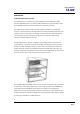
user manual TA-880 INTRODUCTION Turbosound Aspect System Concepts The TA-880 system is a modular point source loudspeaker system designed to deliver extremely high fidelity audio. The system is easily scaleable from large and medium scale ground-stacked and flown concert touring down to small clubs and events. The Aspect system concept centres around the exceptional directivity of the patented Polyhorn™ devices employed in the high frequency and high-mid frequency sections of the mid/high enclosure.
user manual TA-880 The Aspect Polyhorn™ Concept The patented Polyhorn™ design effectively solves the problem of the tendency for exponential horns to beam with increasing frequency. Dividing the multi-cellular horn into multiple tapered waveguides guarantees that the path length of each micro-horn is equal from the surface of the driver diaphragm to the horn mouth, and ensures that all frequencies from all parts of the diaphragm arrive at the horn mouth together.
user manual TA-880 Aspect TA-880 Turnkey System Concept Aspect is available as an integrated audio system package, comprising loudspeakers with integral flying hardware, amplifier racks and all necessary drive and control equipment in an extremely compact and manageable form. In addition, the system has been designed to truck pack efficiently and handle easily.
user manual TA-880 The Loudspeaker Management System (LMS) Concept Turbosound Loudspeaker Management Systems are more than just electronic crossovers. As well as steep slope active filters and high performance limiters, they provide full digital alignment of all components in the Aspect enclosures, to ensure a coherent acoustic output. They also incorporates a number of features which contribute to overall system reliability and ease of setting-up and use.
user manual TA-880 Power Amplifiers In addition to the Turbosound T-25 and T-45 model amplifiers supplied with turnkey Aspect systems, the following other power amplifier brands provide sufficient performance and mechanical compatibility to perform well with Aspect loudspeaker systems: • MC2 E series • Lab Gruppen FP series • Crest Pro series • QSC Powerlight II series Digital Controllers In addition to the Turbosound LMS-D6 and LMS-D26 loudspeaker management systems, the following digital crossov
user manual TA-880 TA-880L Low Frequency Enclosure The TA-880L low frequency enclosure covers the low frequency range from 40Hz up to 100Hz. It contains two very high power 15" neodymium drive units loaded with TurboBass™ devices. The TA-880L is a very compact enclosure and its minimal size and low weight ensures easy handling. It is designed to provide beneficial low frequency coupling when used in multiples. The enclosure is designed to be groundstacked.
user manual TA-880 The Polyhorn™ and TurboMid™ devices are unique to Turbosound and are covered by principle patents world-wide. They utilise specialised forms of horn loading which provide exceptionally low distortion and high efficiency from cone-type drive units. The subjective effect of these devices is greater clarity and transparency of reproduction when compared with conventional compression drivers and horns.
user manual TA-880 Transportation An optional WB-880H wheelboard is available which clips on to the front of the TA-880H cabinet, allowing single units to be conveniently transported. These are designed to be stackable, so that when not in use they can be neatly stored without taking up unecessary floor space. TA-880L bass cabinets are fitted with heavy duty wheels. Optional heavy duty transit covers are available for TA-880H cabinets.
user manual TA-880 Aspect trapezoidal Flying System To take full advantage of the very precise dispersion properties of the Aspect system, an external rigging system has been developed. The flying systems are inherently safe, flexible and simple to use.
user manual TA-880 FLYING AND STACKING Overview The Aspect system flying hardware is specifically designed to take advantage of the precise horizontal directivity characteristics, as well as allow a wide range of adjustment of the vertical angles between adjacent enclosures, and the overall vertical inclination of each column of enclosures. This means that arrays can easily be optimised to suit the coverage requirements of any situation.
user manual TA-880 GIGMATE™ ACOUSTIC SIMULATION While the Aspect System is remarkably intuitive in terms of building arrays and aiming them, and requires no theoretical calculations in order to achieve optimum coverage of a room or audience space due to its inherent ‘point-and-shoot’ nature, there may well be situations where some prior knowledge of a venue can save time in setting up and configuring the PA.
user manual TA-880 The screen is split into four main areas: System Setup The left hand side of the screen is where you define the system, auditorium and project. Tabs On the bottom of this window allow you to toggle between modes. Mapping Properties This is the main window which will display the system as configured in the System Setup window along with the audience areas and mappings.
user manual TA-880 Designing a system To design a system begin by defining the venue/audience areas by clicking on the “Audience Area” tab in the bottom left of the screen. Within this window you can edit or remove existing audience areas, and create new ones. There are two methods of defining an audience area. In either case you must define the X1/Y1 coordinate of the start of the area, you can then either enter the X2/Y2 points or its length and angle.
user manual TA-880 Now select the number of cabinets deep that you wish to hang or stack in the “Box Count” dropdown. Trim height, or PA wing height can now be set in the “Position” field. If a mix of Low and High cabinets are to be used then select in the Cabinet window the type and location in the array of each box. The angle between cabinets can now be set in the “Angle” list. Each cabinet has an aiming line that can be used to determine the centre of each cabinet’s dispersion.
user manual TA-880 Now that the general design has been established the system performance must be mapped. At the top of the main window there is an “SPL Mapping” checkbox. This will map the system output at the frequency and bandwidth selected in the adjacent dropdown boxes. For most applications a 3 octave mapping gives realistic and useful data.
user manual TA-880 The Audience Area graph at the bottom of the window shows the SPL, as specified in the SPL Mapping lists, on the selected Audience Area. The selected area is highlighted in the main window and the graph is repeated onto op each area, Selecting the “Combined Level View” tab will show the SPL across all areas simultaneously. Now that the system is mapped the intercabinet angles or row attenuation may be trimmed to provide the smoothest coverage.
user manual TA-880 Safety Notes on Rigging The Turbosound TA-880 system has been designed and constructed to a high standard of safety, and tested to the most demanding of specifications with a safety factor of 13:1. Always wear protective headwear, footwear and eye protection in accordance with local regulations.
user manual TA-880 Sample Certificate of Load Test TA-880 user manual Page 24
user manual TA-880 FLYING HARDWARE The Aspect TA-880 flying system consists as follows: • Flying swords and safety lynch-pins – support a single cabinet. • Flying chains – link the top row to flybars. • Twin bar – supports two vertical columns.
user manual TA-880 Vertical Coverage Vertical coverage is dictated by the physical dimensions of the room and the location of the audience spaces. The number of boxes required in a vertical column is therefore determined by a number of factors including the trim height of the cluster, the vertical coverage you are trying to achieve, and the distance or projection required.
user manual TA-880 Two-wide trapezoidal flybar FB-880/2W TOPVIEW ENCLOSURE SUSPENSION TAB(WIDE) ENCLOSURE SUSPENSION TAB (NARROW) TILT STRAP POINTS BOTTOM VIEW The FB-880/2W two-wide flybar is a fixed angle double bar designed to fly two vertical columns of cabinets up to four deep per column.
user manual TA-880 Three-wide trapezoidal flybar FB-880/3W TOPVIEW ENCLOSURE SUSPENSION TAB(WIDE) ENCLOSURE SUSPENSION TAB (NARROW) TILTING STRAP POINT (NARROW) TILTING STRAP POINT(WIDE) BOTTOM VIEW The FB-880/3W three-wide flybar is a fixed angle triple bar designed to fly three vertical columns of cabinets up to a total of four deep per column.
user manual TA-880 Flying Chains Flying chains are available in two lengths. FC-880 CHOKED CHAIN ASSEMBLY FC-880S SHORT CHAIN ASSEMBLY The FC-880S flying chain is a short chain designed for linking the top row (or single row) of cabinets to the flybar. It consists of a top hook, chain, connex connector and dagger. The dagger is provided with a single hole for attachment inside the cabinet’s sword box using a safety linch pin.
user manual TA-880 Flying Swords Three types of flying sword are available: • SW-880H swords are used to fly TA-880H mid/high enclosures. • SW-880HM swords are used to fly TA-880HM high-mid enclosures. • SW-880LM swords are used to fly TA-880LM low-mid enclosures. SW-880H FLYING SWORD SW-880HM FLYING SWORD B B A A SW-880LM FLYING SWORD Flying swords are fabricated from steel and are provided with two locating holes at each end, and these allow for a range of vertical inter-cabinet angles.
user manual TA-880 Tilting Strap 0.59m 4m The TS-890 tilting strap is in two parts. The longer part is attached to the tilt strap point on the flying bar using the buckle at its end. The other part of the strap with the ratchet is hooked into the tilt strap point on the rear of the bottom enclosure. The free end is then threaded through the ratchet and the strap tightened to achieve the desired tilt.
user manual TA-880 Flying a single TA-880 trapezoidal cabinet using M10 eyebolts The simplest method of flying a TA-880H cabinet is with a pair of M10 shoulder eyebolts on the top, using a third eyebolt on the rear of the cabinet to tilt the cabinet. 1. Remove the two countersunk M10 screws located just behind the sword slots in the top of the cabinet. 2. Replace these with M10 shoulder eyebolts with a minimum thread length of 20mm (3/4”) 3.
user manual TA-880 Flying a single TA-880 trapezoidal cabinet using FC-880 chains A single cabinet can be flown using a pair of FC-880S short chains and daggers. These simply pass through slots in the top of the cabinet and are secured with safety linch-pins inside the handle boxes. Connect FC-880S short flying chains to the appropriate suspension tabs on the flybar and check that the daggers line up with the slots. In the diagrams below only one dagger is shown for clarity. 1.
user manual TA-880 Flying a vertical column of TA-880 trapezoidal cabinets When flying more than one cabinet deep you will need to use SW-880H swords to suspend and correctly position the second and subsequent cabinets. These make use of the internal sword boxes in the trapezoidal cabinet in the same way as the flying chain and dagger, and ensure that the entire weight of the column is taken through the metalwork and not through the woodwork of the cabinet.
user manual TA-880 3. Position the second cabinet directly underneath the first. Fit a BS-780 biscuit into the top kelping braket of the lower cabinet to keep the backs of the boxes and act as the hinge. Lower the top cabinet and feed the swords into the sword boxes. Make sure that the biscuit engages into the bottom kelping bracket slot of the upper cabinet. The lower end of the swords will be visible through the handle boxes of the lower cabinet. 4.
user manual TA-880 Flying swords are provided with two holes ast each end. This allows for a choice of four incremental vertical angles depending on which hole the linch-pin is located in, and which will determine the combined vertical coverage of the column.
user manual TA-880 Flying a cluster of TA-880 trapezoidal cabinets Aspect trapezoidal flybar configurations offer two basic configurations for assembling arrays, two-wide and three-wide. These configurations will cover the majority of applications, providing up to a maximum 75° of horizontal coverage. For more complex installations or touring applications multiple flybars can be used in a modular fashion.
user manual TA-880 2 wide x 2 deep TA-880H array Parts required: 1 x FB-880/2W flybar 4 x FC-880 choked chain assembly 4 x SW-880H flying sword 4 x SL-880 safety linch-pin 2 x TS-890 tilt strap TA-880 user manual Page 38
user manual TA-880 3 wide x 3 deep TA-880H array Part required: FB-880/3W flybar 6 x FC-880 choked chain assembly 12 x SW-880H flying sword 30 x SL-880 safety linch-pin 3 x TS-890 tilt strap TA-880 user manual Page 39
user manual TA-880 Tight-packed Flying Assemblies When flying single rows of cabinets, especially in installed applications, it is a good idea to configure the boxes in a tight-packed arrangement in order to achieve high power density in a small space. Modular coupling kits are available in two-wide and three-wide configurations in order to facilitate tight-packed flown clusters.
user manual TA-880 The MC-880/3 Modular Coupling Kit consists of three top straps which attach to the box with M10 hex bolts (supplied) and two rear strap with fixes to the rear of the cabinet. These parts when combined hold the cabinets firmly together and they can now be picked up as a single block.
user manual TA-880 Bass Enclosure arraying Aspect bass enclosures are most efficient when ground stacked in a block. Not only do they benefit from improved coupling when there are no air gaps between them, but they also couple to the ground. However, some of this energy may be absorbed by nearby obstructions such as barriers or a tightly-packed standing audience. Sound pressure levels may also be excessive for members of the audience if they are able to get too close to the enclosures.
user manual TA-880 Ground stacking In many situations, indoors or outdoors, it is desirable to ground-stack the system. In this case, the same general rules apply as for flown arrays. High packs should be kept well above head-height and angled carefully for even coverage. A three-wide stack of TA-880H cabinets supported by four TA-880L bass cabinets as pictured below provides an ideal configuration for many situations, giving 75° of horizontal coverage and standing just under 2 metres high.
user manual TA-880 LMS SERIES LOUDSPEAKER MANAGEMENT SYSTEMS Introduction This section is provided with the aim of assisting sound engineers, installers and consultants to fully understand Turbosound Loudspeaker Management Systems, and to obtain the full benefit of their capabilities. The LMS-D6, LMS-D26 and LMS-D24 are recommended for use with Aspect loudspeaker systems, offering varying features and facilities depending on the specific application.
user manual TA-880 LMS-D6 LOUDSPEAKER MANAGEMENT SYSTEM 5 4 LMS-D6 3 MENU ENTER 6 FREQ 9 'Q' GAIN 10 A B 11 1 CLIP TQ-440 GAIN 8 3 LIM -3 MUTE -24 -3 MUTE -24 4 5 6 LIM LIM LIM -3 -3 -3 MUTE -24 -24 -24 OUT DIGITAL LOUDSPEAKER MANAGEMENT SYSTEM 1 2 LIM -6 -24 BYPASS 12 GAIN 7 GAIN GAIN GAIN GAIN GAIN GAIN 2 1. LCD Display - Shows menu options, output information and adjustment parameters. 2.
user manual TA-880 LMS-D6 Rear Panel Functions RS232 DATA INPUT WARNING / AVIS OUTPUT 6 OUTPUT 5 OUTPUT 4 OUTPUT 3 OUTPUT 2 OUTPUT 1 INPUT B INPUT A DO NOT EXP OS E TO RA IN OR MOIST URE THIS EQUIPMENT MUST BE EARTHED SHOCK HAZARD – DO NOT REMOVE CO VERS RISQUE DE CHOC ELECTRIQUE - NE PAS OUVRIR PROTECTION AGAINST FIRE REPLACE ONLY WITH THE SAME TYPE T1A, 250V FUSE 1 2 3 PIN1=SHIELD PIN2=HOT PIN3=COLD CUSTOM MADE FOR TURBOSOUND IN THE UK BY XTA ELECTRONICS 4 5 13. Power Switch. 14.
user manual TA-880 Voltage Settings The LMS-D6 is provided with an auto-seeking power supply, and therefore requires no external adjustment for correct operation with international AC line voltages ranging from 60 to 250 volts. Safety Earthing The green/yellow wire of mains cord must always be connected to the electrical installation's Safety Earth or Ground. It is essential for personal safety, as well as proper operation of the unit.
user manual TA-880 Audio Connections The LMS-D6 audio inputs are RFI filtered and electronically balanced. The outputs are electronically balanced and fully floating. Overall, the unit is designed to operate at any signal levels ranging -10dBu up to +20dBu. The outputs will drive into loads of 600 Ohms or greater and both inputs and outputs are intended to be 'fuss free', regardless of an installation's complexity.
user manual TA-880 LMS-D24 AND D26 LOUDSPEAKER MANAGEMENT SYSTEMS Features • Minimal signal path design, providing exceptional audio quality with carefully optimised processing and high performance converters for a full >111dB dynamic range, 96kHz sampling rate and minimal filtering. Audio-grade capacitors are used in the analogue signal path. • Sonically superb ADC / DAC combination; a carefully matched pairing of the best devices from Burr Brown and Wolfson.
user manual TA-880 Front Panel Functions Channel Select buttons Store and Recall buttons Input Signal Indicators 2x 24 character LCD Limiter Indicators Parameter Edit Encoders Edit Parameter Select buttons Output Mute buttons Input Signal Indicators – A set of three pairs of LED’s indicate signal present, +4dBu and input clip for both channels. The signal present LED’s operate at approximately –40 dBu, giving a useful indication of even relatively low input signal levels.
user manual TA-880 for the current input or output. Text display – preset, channel, parameter and status information is shown on the 2x 24character text display. In most screens the currently selected channel is displayed on the upper line and the edit parameter on the lower line. To simplify the display and enhance security, some parameters or parameter pages are omitted when not relevant. Parameter Knobs – three velocity sensitive parameter knobs are used to adjust parameters shown on the display.
user manual TA-880 Rear Panel Functions Expansion Port Power Inlet Secure Mode Switch Audio Input Connectors Serial Comms Port Audio Output Connectors Power Inlet – provides connection to a suitable mains electricity supply using the cable supplied. The controller has a switch mode power supply that is capable of operating with a nominal mains voltage of 80 to 240v, 50/60Hz without re-configuration. Network expansion port – where a future network card can be fitted.
user manual TA-880 Operating the LMS-D24 and D26 Starting up The unit will energise as soon as power is applied to the IEC inlet; there is no power switch. During the start up process the firmware application model number and version numbers are displayed and the outputs are muted until the unit has completed its internal checks.
user manual TA-880 Navigation and Viewing Parameters (Note: The LMS-D26 is shown in all the following screen shots; however the features and parameters apply equally to the LMS-D24) Many of the processing elements in each input and output path have features that may be controlled by the user, such as gain, frequency or limiter threshold. We call these adjustable features parameters. LMS-D26 In A Freq EQ1 100Hz Width 1.4Q b a a Gain 0.
user manual TA-880 Navigation The DSP parameters are organised by channel. The currently selected channel is shown in the top left hand corner of the display. You can navigate between the channels by pressing the channel buttons. Pressing the channel buttons will scroll through the channels, utilities and back to the default screen. When using a Preset that is stereo linked, the channel selection will reflect this. For example ‘1&4’ indicates outputs 1 and 4.
user manual TA-880 Presets The device contains a total of forty-five user and Factory Presets. The user cannot overwrite the basic mono, basic stereo or Factory Preset programs. Preset Recall To select an existing Preset, press the Recall Button so the indicator above it illuminates. Turn parameter knob A until the required Preset number is shown on the display. Factory presets are indicated by a box symbol appearing after the preset number. Press the Recall Button again to activate the Preset.
user manual TA-880 Preset Store To store the current Preset in a user location, press the Preset Store Button so the indicator above it illuminates. Turn the first parameter knob until the required Preset location number is show on the display. A Preset name of up to 12 characters in length can be entered using parameter knobs B and C. Pressing the Store Button again completes the process and stores the Preset. As with Preset Recall, pressing any other button cancels the operation.
user manual TA-880 DSP Processing Layout Input DSP block diagram Input A Input LED’s Input Gain Delay 4th Order HPF Low Shelf EQ Six Band PEQ High Shelf EQ Routing SUM - 6dB NB.
user manual TA-880 DSP processing Input Channels Gain LMS-D26 In A Gain 0.0dB a c b a Knob A: Gain, adjustable in 0.2dB steps from –80 dB to +20dB Delay LMS-D26 In A Delay 1.50ms a b c a Knob A: Delay, adjustable in variable steps from 0 to 400ms The delay parameter is adjustable in fine steps at low values; the adjustment becomes progressively coarser as the value increases.
user manual TA-880 High Pass Filter LMS-D26 In A Freq Shape HPF 20.0Hz LR24 a a b c b Knob A: Frequency, out (off), 10.0Hz to 25.6kHz in variable steps Knob B: high pass filter type System high pass filtering is provided for the input signal. This is the preferred location for high pass filtering as it affects all outputs and can therefore improve inter-band phase relationships. Filter type is selectable from Butterworth, Bessel, Linkwitz-Riley and Hardman.
user manual TA-880 Parametric Equalisation Eight sections of equalisation are provided, two shelving filters and six fully variable parametric sections. High and Low shelving filters LMS-D26 In A Freq EQ1 100Hz Slope 12dB c b a a Gain 0.0dB b c Knob A: Frequency, 10.0Hz to 25.6kHz in variable steps Knob B: Slope, 6 to 12dB / octave in 1dB steps Knob C: Gain, +/-15dB in 0.2dB steps The frequency is specified as point where the filter deviates by 3dB from the gain value.
user manual TA-880 Output Channels Gain and Polarity LMS-D26 Out1 Gain 0.0dB Pol Rev a a c b b Knob A: Gain, adjustable in 0.2dB steps from –80 dB to +20dB Knob B: Polarity, selectable, normal or reversed with reference to other outputs Delay LMS-D26 Out1 Delay 1.50ms a b c a Knob A: Adjustable in variable steps from 0 to 80ms As for input delay, velocity sensitive Parameter Knobs provide finer adjustment at low levels and rapid selection of higher values.
user manual TA-880 High and Low Pass Filters LMS-D26 Out1 Freq LPF 2.50k Shape LR24 a a b c b Knob A: Frequency, <> Knob B: high pass filter type Filter type is selectable from Butterworth, Bessel, Linkwitz-Riley and Hardman. Filter slopes of up to 8th order or 48dB / octave are provided. Not all filter types are available in all slopes. For example 18dB / octave Linkwitz-Riley filters do not exist.
user manual TA-880 Parametric Equalisation Eight sections of equalisation are provided in a similar format to the input channel equalisation; two shelving filters and six parametric. LMS-D26 Out1 Freq EQ>- 100Hz Slope 12dB a a Gain 0.0dB c b b c Knob A: Frequency, 10.0Hz to 25.6kHz in variable steps Knob B: Slope, 6 to 12dB / octave in 1dB steps Knob C: Gain, +/-15dB in 0.2dB steps The frequency is specified as point where the filter deviates by 3dB from the gain value.
user manual TA-880 Limiters LMS-D26 Out1 Thresh LIM 4.0dB a c b a Knob A: Threshold, -40dBu to 20dBu in 0.2dB steps A high performance, low distortion limiter is provided on each output. Threshold is user adjustable; all other parameters are carefully calculated dependant on configuration to provide clean and effective control of signal dynamics.
user manual TA-880 Utilities Utility functions Two utility functions are provided to adjust screen contrast and the display units used for parametric equalisation bandwidth. The device automatically adjusts for the variations in display contrast as the temperature of the LCD changes. The screen contrast utility control sets the base contrast of the screen and also allows optimization for a given viewing angle.
user manual TA-880 Rear Panel Functions Expansion Port Power Inlet Secure Mode Switch Audio Input Connectors Serial Comms Port Audio Output Connectors Power Inlet – provides connection to a suitable mains electricity supply using the cable supplied. The controller has a switch mode power supply that is capable of operating with a nominal mains voltage of 80 to 240v, 50/60Hz without re-configuration. Network expansion port – where a future network card can be fitted.
user manual TA-880 AMP-890 Aspect System Amplification Rack Ch.A Ch.B Ch.A Ch.B Ch.A Ch.B Ch.A Ch.B Ch.A Ch.B INPUT OR LINK SOCAPEX SOCAPEX LOW OUTPUTS CH 1A CH 1B CH 2A HIGH OUTPU TS CH 2B CH 1 CH 2 Racking, Cables and Connections The AMP-890 Aspect amplification system comprises a complete amplifier rack, flightcase and cabling system which is adaptable to the varying requirements of modern concert touring.
user manual TA-880 Options The rack is supplied fitted with five amplifiers as standard. The two top amplifiers are T-25 models, and power the high frequency and high-mid frequency sections respectively. Three mid-high cabinets will normally be powered from each channel, although it is possible to run up to four cabinets for some extreme applications. The remaining three amplifiers are all T-45 models and power the low-mid frequency and low frequency sections.
user manual TA-880 Figure 1.
user manual TA-880 Figure 2. Mid-High Outputs SOCAPEX PIN NO. CH2 NL8 PIN NO. SOCAPEX PIN NO. CH2 CH1 NL4FC HF+ HF - 01 03 4+ 4- HF+ HF - CHANNEL 1 HF CH2 02 04 4+ 3- 06 08 3+ 3- 13 14 15 16 2+ 2- CHANNEL 2 HF CH1 CH2 CH1 NL4FC NL4FC HM+ HM - 05 07 3+ 3- HM+ HM - CHANNEL 1 HM CH2 NL8 PIN NO. CH1 NL4FC CHANNEL 2 HM CH1 CH2 NL4FC LM+ LM - 09 10 11 12 CH1 NL4FC 2+ 2- LM+ LM - CHANNEL 1 LM CHANNEL 2 LM Figure 3. Bass Outputs SOCAPEX PIN NO. CH2 NL4 PIN NO.
user manual TA-880 Break-out Cables – NL4 bass NL4 PIN NO. SOCAPEX PIN N O.
user manual TA-880 Break-out cables – NL8 mid-high NL8 PIN NO. SOCAPEX PIN NO. 11 NL8 PIN NO. SOCAPEX PIN NO.
user manual TA-880 Mains Connections Incoming mains power may be connected by one of a variety of C Form connectors, depending on the power system specified when the rack was ordered. Typical supply configurations are as follows: 110 V star-wired (3 phase) 110 V parallel (1 phase) 220/240 V (3 phase) 220/240 V (1 phase) The mains power wiring utilises Wago distribution blocks with spring-loaded screwless connectors.
user manual TA-880 T-25 AND T-45 HIGH EFFICIENCY AUDIO POWER AMPLIFIERS General Features & Facilities The T-25 and T-45 are highly efficient, lightweight, rugged high power amplifiers, with many original features developed to meet the requirements of modern professional sound reinforcement, for both touring and fixed installations. They have been designed with audio quality ranking equal first alongside utility and ruggedness.
user manual TA-880 Front Panel Functions T-25 Ch. A Ch.B • Mains power rocker switch – applies AC mains power to the amplifier. • Mains power LED – illuminates when AC power is applied to the amplifier. • Gain – rotary control which allows the gain of the channel to be adjusted. • Signal – blue LED indicates signal presence, active from a minimum output level of 10 watts. TA-880 user manual Page 76 • -3dB – yellow LED is active when the signal is 3dB below the limiting level.
user manual TA-880 Front Panel Functions T-45 Ch. A Ch.B • Mains power rocker switch – applies AC mains power to the amplifier. • Mains power LED – illuminates when AC power is applied to the amplifier. • Gain – rotary control which allows the gain of the channel to be adjusted. • Signal – blue LED indicates signal presence, active from a minimum output level of 10 watts. • -3dB – yellow LED is active when the signal is 3dB below the limiting level.
user manual TA-880 Mechanical Installation When supplied as part of the AMP-890.2 system rack, the amplifiers are pre-installed. If an amplifier is removed from the rack for any reason, it is important to re-install it correctly. The amplifiers must be supported at the front and rear, as originally supplied. Failure to support it adequately may eventually result in vibration-induced metal fatigue of the rack mounting ears and such damage will not be covered by the warranty.
user manual TA-880 Voltage Setting Your models will be set up at the factory for correct operation on your local voltage supply. No further adjustment is necessary. Voltage Range The minimum supply voltage over which the amplifier will operate is 180V for the 220-240V range, and 90V for the 110-120V range. Naturally, maximum power output will be reduced accordingly from the published ratings.
user manual TA-880 The amplifiers are designed to operate with fully balanced equipment. Ground loops or loss of performance may be experienced if connected to unbalanced sources. If it is unavoidable, however, the following wiring convention should be used.
user manual TA-880 Setting higher gain does not change the maximum available power but changes the level of signal input to achieve maximum power. In any case, provided that the input signal is less than 20dBu/7.7V, the built in limiter circuit will prevent distortion within the amplifier. The gain should be set to match the signal from the source, e.g. mixer, controller, or equaliser.
user manual TA-880 Long Speaker Lines Whenever loudspeakers are connected to power amplifiers by long cables (above 20'/6m), there is invariably an increased risk of high frequency instability. It is aggravated by the combination of RF pickup in unshielded cables acting as aerials, and multiple complex reactances in the cable and loudspeakers.
user manual TA-880 APPENDIX A: TECHNICAL SPECIFICATIONS TA-880H TA-880HM TA-880LM Dimensions 1025 x 477 x 463mm 40.3” x 18.8” x 18.3” 477 x 477 x 463mm 18.8” x 18.8” x 18.3” 574 x 477 x 463 18.8” x 18.8” x 18.3” Net weight 59kg (130lbs) 28kg (61.6lbs) 36kg (79.
user manual TA-880 TA-880 user manual Page 84 TA-880L TSW-218 Dimensions 795 x 477 x 574mm 31.3” x 18.8” x 22.6” 574 x 1400 x 770 22.6” x 55.1” x 30.
user manual TA-880 APPENDIX B: WARRANTY All products in this manual are warranted by Turbosound Limited to the original end-user purchaser against defects in workmanship and materials used in its manufacture for a period of one year on electronics products and two years on loudspeaker products from date of shipment to the end user. Faults arising from misuse, unauthorised modifications or accidents are not covered by this warranty. No other warranty is expressed or implied.
user manual TA-880 Turbosound Limited Star Road Partridge Green West Sussex RH13 8RY United Kingdom TA-880 user manual Page 86