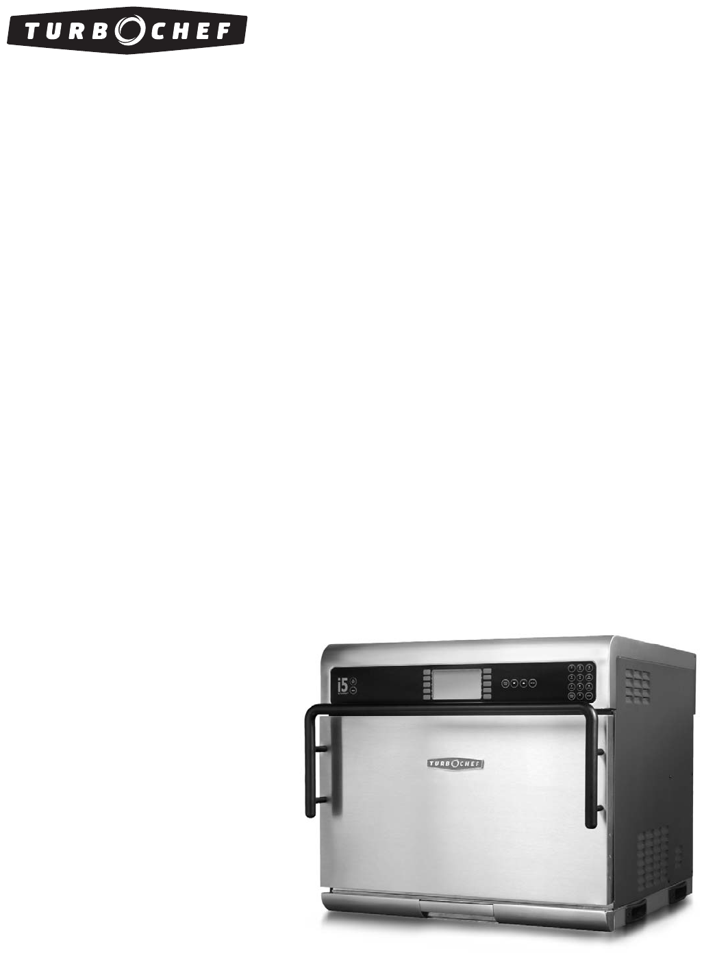
Accelerating the World of Cooking TM Service Manual FOR THE TURBOCHEF i5 RAPID COOK OVEN
For further information, call 800.90TURBO or +1 214.379.
The information contained in this manual is important for the proper installation, use, maintenance, and repair of this oven. Follow these procedures and instructions to help ensure satisfactory baking results and years of trouble-free service. Errors – descriptive, typographic, or pictorial – are subject to correction. Specifications are subject to change without notice. Please carefully read this manual and retain it for future reference.
Table of Contents Safety Instructions General Safety Information Reducing Fire Risk Grounding Instructions Power Cord Replacement Precautions to be Observed Before and During Servicing to Avoid Possible Exposure to Excessive Microwave Energy RF Interference Considerations i i ii ii ii ii Specifications and Installation Theory of Operation Certifications Dimensions Oven Construction Electrical Specifications Unpacking Instructions Lifting and Placing the Oven Installation Near Open Heat Source Optional Ins
Resetting the Oven Turning Oven Options On/Off Setting the Language Setting the Date/Time Test Mode - Testing Oven Parts Test Mode - Status Indicators Test Mode - Fault Log Test Mode - Turning On/Off Diagnostic Mode Test Mode - Self Test Test Mode - Manufacturing Mode Microwave Leakage Test (How to Use Oven for Testing) Microwave Power Test Burn-In Serial Number Edit Changing Temperature Measurement Setting Self Test Erase/Default Oven Settings Loading a Menu Updating the Software 14 14 14 14 15 15 15 15 1
Overview of the Microwave System Capacitors Testing a Capacitor Filament Transformers Wiring the Filament Transformers High-Voltage Transformers Wiring the High-Voltage Transformers Testing a Filament or High-Voltage Transformer High-Voltage Diodes Testing a High-Voltage Diode Magnetrons Testing a Magnetron for an Open/Shorted Filament Stirrer Motor and Assembly Wave Guides Troubleshooting Overview of the Control System Control Board Display Electrical Compartment Cooling Fans Electrical Compartment Cooling
Troubleshooting Overview of Troubleshooting Fault Code Descriptions Fault Code Troubleshooting - F1 Blower Running Status Bad Fault Code Troubleshooting - F2 Cook Temperature Low Fault Code Troubleshooting - F3 Magnetron Current Low Fault Code Troubleshooting - F4 Door Monitor Defective Fault Code Troubleshooting - F5 Magnetron Over Temperature Fault Code Troubleshooting - F6 Electrical Compartment Temperature High Fault Code Troubleshooting - F7 Open RTD Fault Code Troubleshooting - F8 Heat Rise Low Non-Fa
i Safety Instructions Strictly adhere to the following safety precautions to reduce the risk of burns, electric shock, fire, injury, damage to oven or property near oven, or possible exposure to excessive microwave energy. General Safety Information Read all instructions before using this appliance. Read and follow the specific "Precautions to be Observed Before and During Servicing to Avoid Possible Exposure to Excessive Microwave Energy" found on page ii. This appliance must be grounded.
ii SAFETY INSTRUCTIONS Grounding Instructions This appliance must be grounded. In the event of an electrical short circuit, grounding reduces the risk of electric shock by providing an escape wire for the electric current. This oven is equipped with a cord that has a grounding wire with a grounding plug, which must be plugged into an outlet that is properly installed and grounded.
Specifications and Installation
1 31.1” (790 mm) 27.2” (691 mm) 43.4” (1102 mm) 28.25” (718 mm) 24.3” (618 mm) Figure 1: i5 Oven Dimensions Theory of Operation Dimensions The i5 rapid cook oven combines preciselycontrolled impinged air and microwave energy to create higher heat transfer rates than conventional ovens. Top-launched microwave and impinged air are stirred to further ensure even heat distribution, while impinged air enters the cavity from the top and bottom, generated by dual independentlycontrolled blower motors.
2 SPECIFICATIONS AND INSTALLATION Electrical Specifications TurboChef recommends a Type D circuit breaker for all installations outside the US.
3 Figure 2: Hand Grip Locations Install or locate this appliance only in accordance with the instructions below. Unpacking Instructions 1. Remove oven from packaging. 2. Before discarding packaging, check thoroughly for accessories, consumables, and literature. 3. Discard packaging. 4. Check cook cavity thoroughly for accessories, consumables, and literature. Discard any packaging. Lifting and Placing the Oven WARNING: Oven weighs approximately 275 lbs (125 kg). Never lift with fewer than two people.
4 SPECIFICATIONS AND INSTALLATION Installation Near Open Heat Source See Figure 4, page 5. When placing a TurboChef oven near an open heat source, strictly adhere to the following: - If the oven is being placed near a grill or stove, a divider must exist between the oven and the open heat source, with a minimum of 6” (152 mm) between the oven and the divider.
5 Counter Top / Table Partition 24.3” (618 mm) Above Counter Top Partition 24.3” (618 mm) Above Counter Top TurboChef i5 Oven Grill Deep Fryer 6” (152 mm) Minimum 12” (305 mm) Minimum Figure 4: Installation Near Open Heat Source 32.0” (813 mm) Figure 5: Oven Cart Dimensions 26.625” (676 mm) SPECIFICATIONS AND INSTALLATION 27.
6 SPECIFICATIONS AND INSTALLATION This page intentionally left blank.
Daily Maintenance
7 Daily Maintenance Supplies and Equipment The following steps will help maintain your i5 Oven. Use only TurboChef Oven Cleaner and Oven Guard. The use of any other cleaning products can damage critical oven components, resulting in a non-warranty service call.
8 DAILY MAINTENANCE Step 7: Clean and Dry the Oven Door CAUTION: DO NOT spray oven cleaner directly onto the oven door gasket (reference “A” in adjacent photo) or saturate it with water. A Step 7 CAUTION: DO NOT scrub or attempt to clean the oven door gasket. Doing so may cause the oven door to misalign, resulting in a non-warranty service call. - Clean oven door with oven cleaner and a nylon scrub pad. - Wipe the oven door with a damp towel.
Oven Controls and Cooking
9 1 4 4 BACK 2 3 ABC DEF 4 5 6 GHI JKL MNO 7 8 9 PQRS TUV WXYZ BACK 0 ENTER ENTER STOP S TO P 1 2 3 5 6 7 8 Figure 6: Oven Controls Oven Controls 1. Info Key When the oven is off or cooling down, press to access the INFO MODE (see page 13). 5. Back/Stop Key When the oven is cooking, press the Back/Stop key to immediately terminate a cook cycle. When the oven is in the IDLE MODE (see page 11, MODE 5) or the INFO MODE (see page 13), press to return to the previous screen.
10 OVEN CONTROLS AND COOKING 1 5a 8 GROUP 1 OVEN OFF GROUP 2 READY TO CLEAN GROUP 3 COOKING DONE SETPOINT: 500F PLEASE REMOVE FOOD FROM OVEN GROUP 4 GROUP 5 2 5b SELECT COOK TEMPERATURE 9 RECIPE 6 RECIPE 1 RECIPE 2 450F RECIPE 3 RECIPE 8 375F RECIPE 4 RECIPE 9 350F RECIPE 5 RECIPE 10 3 GROUP 1 COOK MORE BROWN MORE COOK AND BROWN MORE SAVE ADJUSTED TIME 6 WARMING UP ADDITIONAL COOKING OPTIONS RECIPE 7 500F EXIT 10 COOLING DOWN ADJUST TIME OVEN TCC = 244F SET POINT= 500F PL
11 Happens When... - The oven completes MODE 10. Goes To... - MODE 2 when On/Off key is pressed. - INFO MODE (page 13) when Info key is pressed. Mode 2: Temperature Select NOTE: If cooking with only one temperature, this screen will be bypassed. The i5 Oven can store up to four different cook temperature settings. Each temperature setting has 5 food groups assigned to it, each consisting of 10 food recipes (50 recipes per temperature setting).
12 OVEN CONTROLS AND COOKING The ADJUST TIME MODE can be turned on or off from the “Options” screen (see page 14). It is turned off by default. Happens When... - ADJUST TIME MODE is enabled and a food item is selected from MODE 5. Goes To... - MODE 7 when “Start Cook” is selected. - MODE 10 if the On/Off key is pressed. Mode 7: Cooking Mode during which the oven cooks a food item. NOTE: To immediately terminate a cook cycle, press the Back/Stop key.
13 Overview of the Info Mode The INFO MODE serves four main purposes: 1. To display oven information. 2. To provide access to TEST MODE and additional diagnostic tools for service technicians. 3. To turn oven options and features on/off. 4. To update oven settings. To access the INFO MODE, simply press the Info key when the oven is either off or cooling down. The INFO MODE consists of two screens. To toggle between screens, press the Up key or Down key.
Info Mode
14 INFO MODE Resetting the Oven Setting the Date/Time Resetting the oven is one way to potentially clear an error message, should one occur. From screen 1 of the INFO MODE, press the R5 soft key. Figure 13. Turning Oven Options On/Off Figure 12. From screen 2 of the INFO MODE, press the L2 soft key to access the “Options” screen. When prompted, enter the password 9 4 2 8 and press the Enter key.
15 Test Mode - Testing Oven Parts Test Mode - Status Indicators From screen 2 of the Info mode, press the L1 soft key to access TEST MODE. When prompted, enter the password 9 4 2 8 and press the Enter key. Figure 14.
16 INFO MODE Test Mode - Self Test From TEST MODE, press the R4 soft key to access the “Self Test” screen (Figure 15). From the “Self Test” screen: - L1 soft key initiates a comprehensive self test. The oven will check the door switches, blowers, magnetrons, and heaters in sequence. - L2 soft key initiates a door switch test only. - L3 soft key initiates a blower test only. - L4 soft key initiates a magnetron test only. - L5 soft key initiates a heater test only.
17 Serial Number Edit Loading a Menu Press the L4 soft key to access the “Edit Serial Number” screen. To edit the serial number: - Use the number/letter keys to change a character. After one second, the cursor will advance to the next character. - Press the R3 soft key to advance to the next character. - Press the L3 soft key to return to the previous character. - Press the R5 soft key to save the changes or the L5 soft key to cancel.
18 INFO MODE Updating the Software From the Oven Off screen, 1. Insert the smart card (see Figure 21). If multiple smart cards are required, ensure the correct smart card is loaded first. 2. From the COOLING DOWN or OVEN OFF mode, press and hold the Info key until the oven resets (approximately 5 seconds). 3. When the oven beeps one long high tone, the load was successful. If a second card was provided, insert it. 4. When the oven restarts and the display turns on, the update is complete.
Edit Mode
19 Overview of the Edit Mode Single vs. Multiple Temperature Mode The EDIT MODE serves three main purposes: 1. To edit set temperatures. 2. To edit names of food groups and recipes. 3. To edit recipe settings. The i5 Oven is capable of utilizing four unique set temperatures. By default, the oven operates in “Single Temperature” mode, in which all four temperatures are the same. By contrast, if more than one temperature is specified in the EDIT MODE, the oven will operate in “Multiple Temperature” mode.
20 EDIT MODE Changing Set Temperatures Changing Food Group/Recipe Name If a menu was loaded via smart card or USB (page 17), the temperatures are already set - they need not be changed. The set temperature should never be changed during normal operation. To change a food group or recipe name, 1. Place the oven in EDIT MODE (see page 14). 2. Select a “block” of food groups by pressing the corresponding right-side soft key (Figure 22).
21 Changing Recipe Settings Recipe settings consist of the following: - Up to eight “events” or stages of the cook cycle. - Cook time. To change recipe settings, 1. Place the oven in EDIT MODE (see page 14). 2. Access the “Food Group” screen (page 20). 3. Select a recipe to edit (Figure 24). 4. Use the Down key to move the cursor to the desired “Event Setting” field (Figure 25). NOTE: To help make navigation easier, the currently-selected field will be displayed in the top-right corner of the display.
22 EDIT MODE This page intentionally left blank.
Oven Systems
23 Convection System Heater Element The convection system is designed to rapidly heat, clean, and recirculate air into the cook cavity. The main convection heater is a finned-style heater rated at 3000 watts at 208 VAC with a resistance of 14.4 Ohms. The convection heater is controlled by the K4/K5 solid state relay.
24 OVEN SYSTEMS Troubleshooting Convection System The following faults may occur in relation to the convection system: - F1: Blower (see page 39) - F2: Low Temp (see page 40) - F6: EC Temp (see page 43) - F7: Thermo (see page 43) - F8: Heat Low (see page 44) The following cooking performance issues may occur in relation to the convection system: - Food not browning properly (see page 47) 5.
25 Oven Frame Oven Frame Remove Bolts Remove Bolts SM Switches Oven Door P Switch Hinge Hinge Oven Door Figure 26A: Properly Adjusted Door - Side Views Tap in this corner Tap in this corner Figure 26B: Door Misaligned Variation 1 - Side Views Figure 26C: Door Misaligned Variation 2 - Side Views OVEN SYSTEMS First remove switches, then tap here
26 OVEN SYSTEMS Interlock Switches The primary, secondary, and monitor interlock switches engage and disengage in sequence to ensure a proper seal. When the door is opened, the switch sequence is P, S, M. Subsequently, the sequence is M, S, P when the door is closed. Adjusting the Door Switches WARNING: Procedure requires work while the oven is hot. As a result, exercise extreme caution when adjusting the door switches. 1. Ensure the oven door is closed. 2. Verify the oven door is not misaligned.
27 Step 5 = Loosen, Step 7 = Tighten, Step 8 = Loosen Slightly Step 4 Step 6: Notch should rest against side of bracket. Step 6: Thin side of spacer fits between screw and bracket. Step 4 Step 3 Step 3 Figure 27: Counter Balance Adjustment Measuring RF Leakage for Microwave Safety WARNING: Procedure requires work while the oven and water loads are hot. As a result, exercise extreme caution when testing.
28 OVEN SYSTEMS Figure 28: Survey Meter Placement 5. Close the oven door and press the Enter key. The microwave system will turn on. 6. Position the microwave survey meter as shown in Figure 28, above. 7. Measure microwave emission around the door, moving the meter sensor at 0.5 inches/second. As microwave leakage is observed moving the sensor at 0.5 inches/second, note any meter spike areas that come close to 5mW/cm2 for later re-measurement. 8.
29 Microwave System The i5 oven employs two independent microwave systems (left and right). In the case of an overcurrent situation relative to the left system, the F3 fuse will blow. In the case of an over-current situation relative to the right system, the F4 fuse will blow.
30 OVEN SYSTEMS To verify correct wiring (International), measure the voltage between the taps on FT1 and FT2. The voltage must be 220 VAC (Latin America), 200 VAC (Japan), or 230 VAC (International). The wiring issue must be corrected prior to returning the oven to service, as the voltages must be: - NORTH AMERICA: 208 VAC between 1 & 2 and 240 between 1 & 3.
31 High Voltage Transformers Primary Voltage, Frequency, Taps, and Resistance Secondary Taps and Resistance NGC-3062-1 208 VAC, 60 Hz, 1 & 2, 0.819–1.001 W 4, Ground, 53.60–65.52 W 240 VAC, 60 Hz, 1 & 3, 0.972–1.188 W NGC-3062-2 230 VAC, 50 Hz, 1 & 2, 0.972–1.188 W 3, Ground, 57.52–70.30 W NGC-3062-3 200 VAC, 50/60 Hz, 1 & 2, 0.784–0.958 W 3, Ground, 55.75–68.
32 OVEN SYSTEMS Magnetrons Figure 30. Magnetrons supply the RF energy at 2.45 GHz and begin to oscillate when they are supplied with approximately 4.1 kVDC at approximately .350 mA. During operation each magnetron will output a nominal 1 kW of power. If replacement is required, conduct a microwave leakage test (page 27) after installation of new magnetron. FA F FILAMENT AND HIGH VOLTAGE TERMINALS 4.
33 Control System This section contains information about the following components: - Control board - Display - Electrical compartment cooling fans - Electrical compartment cooling fan thermostat - Electrical compartment thermocouple - EMI Filter - Fuses - High-limit thermostat - Keypad - Magnetron cooling fans - Magnetron thermostats - Power Supply - Relay (K1 - Filament) - Relay (K2 - Anode) - Relay (K3 - Monitor) - Relay (K6 - Voltage) - Relay (K7 - Mag fan) - Relay (K8 - Stirrer) - RTD - Smart card rea
34 OVEN SYSTEMS High Limit Thermostat Magnetron Thermostats The high limit thermostat is a 250 VAC, 3-pole, manual-reset thermostat with a trip point of 572ºF (300ºC). The thermostat interrupts power to the main convection heater in the event of an abnormal condition. The magnetron thermostats are “open-on rise.” They are designed to open at 212ºF (100ºC), which triggers an F5 fault. Reset the high-limit thermostat by pressing the reset button (Figure 31).
35 Relay - K7 Magnetron Cooling Fan USB Port The K7 relay is a 240 VAC, 30 amp, double-pole, double-throw, 24 VDC relay coil. It switches power to the magnetron cooling fans when the magnetron filaments are actuated. Power is switched off after 4 minutes, 15 seconds. The USB port allows the oven operator to load a menu/software updates from a USB drive. A menu that already exists in the oven can also be saved to a USB drive. For instructions, see page 17.
36 OVEN SYSTEMS Filtering System Drain Pan This section contains information about the following components: - Catalytic converter - Drain pan - Air Filter - Vent catalyst The drain pan collects debris as it is flushed through the bottom of the cook cavity. Catalytic Converter The catalytic converter, a VOC type catalyst, is located behind the inside cook cavity wall and is responsible for cleaning the recirculating airflow.
Troubleshooting
37 Overview of Troubleshooting This section contains information on the following: - Fault code descriptions - Fault code troubleshooting - Non-fault code troubleshooting For information on accessing TEST MODE, see page 15. For information and illustrations on replacing components, see the appendix. Fault Code Descriptions For instructions on viewing the fault counter, see page 13. F1: Blower Running Status Bad This fault is displayed when the motor controller indicates no running status.
38 TROUBLESHOOTING F7: RTD Open This fault is displayed when the control detects that the RTD is “open.” The display will show a reading of “999ºF/C,” indicating the RTD is open. F8: Heat Low This fault displays during WARMING UP or TEST MODE if the cook cavity temperature fails to rise at least 14ºF (7ºC) within a given 30 seconds. The fault is cleared when the control detects continuity. Fault Code and Description When Active Warmup F1: Blower Running Status Bad Refer to...
39 Fault Code Troubleshooting From TEST MODE, you can run oven diagnostics and check fault counts. To access TEST MODE or turn on Diagnostic mode, see page 15. Troubleshooting: F1: BLOWER (Blower Running Status Bad) Is the wiring harness properly connected? YES Check the motor controller, top and bottom blower motors, and I/O control board. (See page 51 for schematic.
40 TROUBLESHOOTING Troubleshooting: F2: LOW TMP (Cook Temperature Low) Reset and determine why it tripped – excess grease buildup, etc. (Figure 31, page 34) YES Is the high-limit thermostat tripped? NO Is either of the heater elements defective? (heaters should have a resistance of 14.4 Ohms) YES NO Replace the defective heater.
41 Troubleshooting: F3: MAG CURR (Magnetron Current Low) Is control board detecting 10A or more current? Test for 24 VDC on pin 2 of J7 connector (page 51). YES Intl. Is the oven U.S. or International? Is the K6 mechanical relay in good working order? U.S. YES Replace the control board. See page A-8. Check the condition of the F3 and F4 fuses (pages 42, A-5 through A-6).
42 TROUBLESHOOTING Troubleshooting: F4: MONITOR (Door Monitor Defective) NO Are the switches opening in the correct sequence (P, S, M)? To access TEST MODE or for info on status indicators, see page 15. YES Is the F3 or F4 fuse blown? NO Replace the F3 or F4 fuse (see page A-5 through A-6). Readjust the monitor safety switch. See page 26 for instructions. Disconnect oven from power supply and then reconnect. The fault should clear. YES Disconnect oven from power supply and then reconnect.
43 Troubleshooting: F6: EC TEMP (Electrical Compartment Temperature High) YES Does the oven have room to ventilate? Required clearances: Top: 16” (406 mm) Sides: 2” (51 mm) NO YES Are both cooling fans rotating? NO Is the oven in an area of moderate temperature (120ºF (49ºC) or cooler)? NO Move oven to open area or remove items that are in close proximity. Is the wire harness properly connected? Check cooling fan thermostat and cooling fans. (See page 51 for schematic.
44 TROUBLESHOOTING Troubleshooting: F8: HEAT LOW YES Is the high-limit thermostat tripped? YES Reset (page 34) and determine why it tripped – excess grease buildup, etc. NO Are both blower motors moving air? Check in TEST MODE - see page 15. NO Is the heater defective? Check in TEST MODE - see page 15. YES Replace defective heater. (page A-11) Verify the solid state relay is not shorted across output.
45 Non-Fault Code Troubleshooting This section provides troubleshooting tips for issues that may occur independently of an oven fault. Troubleshooting: No Keypad Input YES Is the keypad cable properly connected to the control board? NO Replace the keypad (page A-5 through A-6). If the problem persists, replace the control board (page A-8). Correct wiring. Troubleshooting: “Cook Door Open” Message when Door is Closed Verify the action of the trailing arm.
46 TROUBLESHOOTING Troubleshooting: No Display – Screen is Blank YES Does the keypad beep when a key is pressed? Replace the fuses. (page A-5 through A-6) Is wiring from the control board to the display OK? NO Is pin 1 on the J7 connector receiving 5 VDC? (see schematic, page 51) YES Replace the display (page A-8). NO NO Is the power supply receiving power? YES Correct wiring. If ribbon cable is damaged, replace the keypad (page A-5 through A-6). Replace the power supply (page A-5 through A-6).
47 Troubleshooting: Food Not Cooking Properly Does the problem occur for all programmed recipes? For example, are all recipes undercooked/overcooked/etc.? YES Are there any fault codes present? See page 37. Troubleshoot the fault(s) using the steps on pages 37-44. NO Is the food item in the correct starting state (e.g., frozen, fresh, etc.)? YES Is the menu part number and revision correct? Verify with customer or contact TurboChef Customer Service.
48 TROUBLESHOOTING Troubleshooting: “Read Fail” Message When Loading Menu Smart Card Does a backup copy of the menu work? NO Did you use a smart card or USB device? Is the file named correctly (menudata.bin) and in the correct location (TC_Menus)? No backup copy If the menu card was created by TurboChef, obtain a new menu card by contacting customer service at 800.90TURBO or +1 214-379-6000.
49 Troubleshooting: “Write Fail” Message When Loading Menu Smart Card Are you trying to write to a smart card or USB device? USB Device Does the USB device contain a top-level folder named “TC_Menus”? Try writing to a new smart card. Was the write successful? NO YES NO Is the connection from smart card reader to control board OK? On the USB device, create a top-level folder named “TC_Menus”.
50 TROUBLESHOOTING Troubleshooting: “Defective Media” Message When Oven is Plugged in or Restarted YES Unplug the oven and then plug it back in. Did this fix the problem? NO Check for microwave leakage (page 27). If no leakage is found, replace the control board (page A-8). Does the message prevent the oven from reaching the “Oven Off/ Cooling Down” screen? YES NO Operate the oven as you would normally.
Oven Schematic
51 DWG NO SH i5-9100 1 REVISIONS QC4 1 P RIMARY INTERLOCK NC C MONITOR SWITCH OT2 C C-10 FAN2 (COOLING/REAR) 4 NOTE: ALL 50 HZ OVENS HAVE 230VAC TRANSFORMERS( TAPS 1-2 ARE CONNECTED) 3 9 6 C-16 K6 (VOLTS) 7 B17-K1-A (+24 VDC OUTPUT)/RED B16-K8-B(STIRRER)/WHITE A (240) (208) 3 (240) 6 (208) 2 1 3 . 19UF C2 . 91UF HV TRANSFORMERS (C) B C21-K4-A2 (HEATER)/WHITE 1 C-12 4 (QC9 RTD) 2.2K 1/2W 3 6 B-17 E4 E3 MODULE BLK GRAY BRN BLU GRN 1 HX 2 (3000 W/14.
52 This page intentionally left blank.
Appendix - Replacing Oven Components
A-1 Comprehensive Table of Oven Components DANGER: Before replacing any oven component, ensure the oven is removed from any power source. Replacing a component while the oven is plugged in can result in serious injury or death. NOTE: For hardware, see the illustrations contained in this appendix. To Replace This... First Remove This...
A-2 APPENDIX - REPLACING OVEN COMPONENTS To Replace This... First Remove This...
A-3 To Replace This... First Remove This...
A-4 APPENDIX - REPLACING OVEN COMPONENTS Figure Item Description Reference # Item Part Number Hardware Description Hardware Part Number(s) 10 Jetplate (Top) I5-9203 None None 11 Lower Front Panel i5-9246 None None 12 Rack I5-9168 None None 13 Rack Support I5-9165 Screw, Sh Mtl #8 x 1/2, Serrated PHTRH 101688 (qty 4) 14 Shunt Plate Assembly I5-9307 Screw, 6-32 x .
A-5 1 8 2 3 4 5 6 9 10 7 18 11 12 13 14 15 16 17 Figure A-3: Opening Top Cover Required DANGER: Before replacing any oven component, ensure the oven is removed from any power source. Replacing a component while the oven is plugged in can result in serious injury or death. CAUTION: Before removing/installing any component, make sure it is disconnected from the wire harness (where applicable). NOTE: Hardware listed is required for installing component to oven. To open the top cover: 1.
A-6 APPENDIX - REPLACING OVEN COMPONENTS Figure Item Description Reference # Item Part Number Hardware Description Hardware Part Number(s) 1 Cover, Top I5-9243 Screw, #10-32 x 3/8 lg, PFLH, 100 Deg, SS 101401 (qty 2) 2 Fuse, F1, 12-amp 100592 None None 3 Fuse, F2, 12-amp 100592 None None 4 Fuse, F3, 12-amp 100592 None None 5 Fuse, F4, 12-amp 100592 None None 6 Fuse Holder 103548 Screw, #8-32 x 3/8, PPHD, Int Sems, SS 102921 (qty 4) 7 Heat Shield/Support Bracket I5-9224
A-7 Replacing Items - Removing Top Cover Required (Figures A-4, A-5, A-6) DANGER: Before replacing any oven component, ensure the oven is removed from any power source. Replacing a component while the oven is plugged in can result in serious injury or death. CAUTION: Before removing/installing any component, make sure it is disconnected from the wire harness (where applicable). NOTE: Hardware listed is required for installing component to oven. To remove the top cover: 1.
A-8 APPENDIX - REPLACING OVEN COMPONENTS 3 17 10 12 Figure A-6: Top Cover Detail Figure Item Description Reference # Item Part Number Hardware Description Hardware Part Number(s) 1 Capacitor, High-Voltage 100232 None None 2 Capacitor Clamps 100134 Screw, Sh Mtl #8 x 1/2, Serrated PHTRH 101688 (qty 2) 3 Control Board CON-7002 Nut, Keps, Hex, #6-32, Ext Tooth, Cres 102961 (qty 4) 4 Cooling Fan (Exterior) TC3-0433 Screw, Sh Mtl #8 x 1/2, Serrated PHTRH 101688 (qty 2) 5 Cooling Fa
A-9 Replacing Items - Removing Left Side Cover Required (Figures A-7, A-8) DANGER: Before replacing any oven component, ensure the oven is removed from any power source. Replacing a component while the oven is plugged in can result in serious injury or death. CAUTION: Before removing/installing any component, make sure it is disconnected from the wire harness (where applicable). CAUTION: Be careful to not tear the insulation when servicing components.
A-10 APPENDIX - REPLACING OVEN COMPONENTS 3 1 12 8 13 5 2 9 6 10 11 7 Figure A-7: Removing Left Side Cover Required 1 8 3 2 Figure A-8: Blower Motor Assembly 8 4
A-11 Replacing Items - Removing Right Side Cover Required (Figure A-9) DANGER: Before replacing any oven component, ensure the oven is removed from any power source. Replacing a component while the oven is plugged in can result in serious injury or death. CAUTION: Before removing/installing any component, make sure it is disconnected from the wire harness (where applicable). NOTE: Hardware listed is required for installing component to oven. To remove the right side cover: 1.
A-12 APPENDIX - REPLACING OVEN COMPONENTS Replacing Items - Removing/Opening Multiple Covers Required (Figures A-10, A-11) DANGER: Before replacing any oven component, ensure the oven is removed from any power source. Replacing a component while the oven is plugged in can result in serious injury or death. CAUTION: Before removing/installing any component, make sure it is disconnected from the wire harness (where applicable). NOTE: Hardware listed is required for installing component to oven.
A-13 13 15 16 14 17 19 18 20 Figure A-10: Removing/Opening Multiple Covers Required 8 4 11 10 3 12 1 5 6 9 2 Figure A-11: Counter Balance Assembly, Hinge, and Switch Detail APPENDIX - REPLACING OVEN COMPONENTS 7
For service or information: W I T H I N N O RT H A M E R I C A C A L L Customer Service at 800.90 T U R B O or O U T S I D E N O RT H A M E R I C A C A L L +1 214-379-6000 or Your Authorized Distributor Accelerating the World of Cooking TM Part Number: i5-9231/Revision B/March 2008 Country Code: NA/EU Corporate Headquarters Global Operations Six Concourse Pkwy, Suite 1900 Atlanta, Georgia 30328 U S A +1 678.987.1700 P H O N E +1 678.987.