C3/AB, C3/C, C3Multi, C3/CMulti CONVECTION MICROWAVE OVEN SERVICE AND REPAIR MANUAL TURBOCHEF TECHNOLOGIES INC. www.turbochef.com 10500 Metric Drive, Suite 128, Dallas, Texas 75243 USA (800) 908 TURBO (8-8726) © 2004 - TurboChef Technologies Inc . PN: TC3-0215 Rev.
TurboChef Technologies, Inc. This page intentionally left blank.
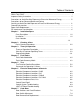
Table of Contents READ THIS FIRST …………………………………………………………………………… i Important Safety Instructions ……………………………………………………………….. ii Precautions to Avoid Possible Exposure to Excessive Microwave Energy ……………. iii Precautions to be Observed Before and During Servicing to Avoid Possible Exposure to Excessive Microwave Energy ………………. iv Grounding Instructions ………………………………………………………………………. v Power Cord Replacement …………………………………………………………………… v RF Interference Considerations ……………………………………………………………..
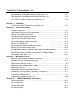
TurboChef Technologies, Inc. Door Removal and Replacement Left Side Parts List Door Removal and Replacement Right Side Parts List C3/C AND C3/CMULTI Door Assy and Parts List 7-13 7-16 7-18 Chapter 7 Cook Door C3/AB and C3MULTI Door Assy and Parts List 7-21 Chapter 8 Convection Circuit Catalytic Converter ………………………………………………………………. 8-2 Convection Element and Thermocouples ……………………………………… 8-3 How to Turn Heaters ON & OFF …………………………………………. 8-4 Changing Heater Operating Voltage ………………………………………….
READ THIS FIRST Before working on the TurboChef Technologies, Inc. C Series oven you must first read the safety instructions on the following pages. The C3 series oven is a combination convection/microwave oven. While servicing this oven, an RF meter must be used at all times to check for microwave leakage. This RF reading must be recorded on your work invoice. Very often poor cleaning will result in microwave leakage.
IMPORTANT SAFETY INSTRUCTIONS WHEN USING ELECTRICAL APPLIANCES, THE FOLLOWING BASIC SAFETY PRECAUTIONS SHOULD BE STRICTLY ADHERED TO: 1. 2. 3. 4. 5. 6. 7. 8. 9. 10. 11. 12. 13. 14. 15. 16. 17. WARNING!! To reduce the risk of burns, electric shock, fire, injury to persons or exposure to excessive microwave energy: Read all instructions before using the appliance. Read and follow the specific PRECAUTIONS TO AVOID POSSIBLE EXPOSURE TO EXCESSIVE MICROWAVE ENERGY found on pages iii & iv.
PRECAUTIONS TO AVOID POSSIBLE EXPOSURE TO EXCESSIVE MICROWAVE ENERGY 1. DO NOT attempt to operate this oven with the door open since open-door operation can result in harmful exposure to microwave energy. It is important not to defeat or tamper with the safety interlocks. 2. DO NOT place any object between the oven front face and the door or allow soil or cleaner residue to accumulate on the sealing surfaces. 3. DO NOT operate the oven if it is damaged.
PRECAUTIONS TO BE OBSERVED BEFORE AND DURING SERVICING TO AVOID POSSIBLE EXPOSURE TO EXCESSIVE MICROWAVE ENERGY 1. DO NOT operate or allow the oven to be operated with the door open. 2. Make the following safety checks on all ovens to be serviced before activating the magnetron or other microwave source, and make repairs as necessary: a) Interlock operation. b) Proper door closing. c) Seal and sealing surfaces (arcing, wear, and other damage). d) Damage to or loosening of hinges and latches.
GROUNDING INSTRUCTIONS This appliance MUST BE grounded. In the event of an electrical short circuit, grounding reduces the risk of electric shock by providing an escape wire for the electric current. This appliance is equipped with a cord having a grounding wire with a grounding plug. The plug must be plugged into an outlet that is properly installed and grounded. WARNING!! Improper use of the grounding can result in a risk of electric shock.
RF INTERFERENCE CONSIDERATIONS This oven generates radio frequency signals. This device has been tested and determined to be in compliance with applicable part of FCC part 18 requirements and to the protection requirements of Council Directive 89/336/EEC on the approximation of the laws of the Member States relating to electromagnetic compatibility at the time of manufacture. However, some other equipment may exhibit sensitivity to signals below these limits resulting in interference with that equipment.
CHAPTER 1 INSTALLATION SPECS
TurboChef Technologies, Inc. C series OVEN DESCRIPTION SPECIFICATIONS C3/AB, C3MULTI, C3/C, AND C3/CMULTI Dimensions (single unit) 29” W x 25.5” H x 29.5” D (73.66 cm x 64.77 cm x 74.93 cm) Dimensions (double stacked units) 29” W x 43” H x 29.5” D (73.66 cm x 109.22 cm x 74.93 cm) Maximum Input 7.
Installation Specs OVEN LOCATION The well planned and proper placement of your oven will result in long term operator convenience and satisfactory performance. Be sure to place the oven in an area which is accessible for proper operation and servicing. The countertop or work surface must be able to support the weight of 250 pounds. The manufacturer shall not assume liability for damage or injury resulting from improper installation of equipment including temporary or unstable work stations or countertops.
CHAPTER 2 CLEANING & OPERATING
TurboChef Technologies, Inc. C Series BASIC CLEANING PROCEDURES PROBLEMS ASSOCIATED WITH IMPROPER CLEANING The oven may not be operating correctly because it is not being cleaned properly. If the door is leaking microwaves, erratic operation of the display and other electrical components can occur. Also food deposits left in the oven will turn into black carbon from the high heat. Carbon can cause arcing inside the cooking area and can reflect energy back to the magnetron.
CHAPTER 3 THEORY OF OPERATION
TurboChef Technologies, Inc. C Series INTRODUCTION The TurboChef C3/C oven utilizes two independent heat transfer mechanisms in order to rapidly cook food. The systems are as follows: Convection and Microwave energy. By combining these mechanisms and with our ability to control each mechanism independently, we are able to reduce the cook time of most foods by 70%-90%. For the purpose of this manual we will identify each independent heat transfer mechanism individually.
Theory of Operation GLOSSARY OF COMMON OPERATING TERMS Display - Primary interface to relay messages to the operator. Keypad - Primary interface for the operator to control the oven. Cook Temperature Set Point Temperature should be a constant parameter. The same cook temperature should be used by all cook recipes. MODES PRODUCT RECIPES Mode – The software environment which allows certain operations to occur. There are several modes, STANDBY, COOK, WARM UP and COOL DOWN in which the oven can operate.
TurboChef Technologies, Inc. C Series Programing EDIT GROUPS Edit Mode GROUP A GROUP E Edit mode enables the operator to alter Recipes and the Cook Chamber Temperature (CC). To Access Edit Mode, press the “Up” and “Down” Arrows Keys on the keypad simultaneously. When prompted, enter the Access Code “9” and then press “Enter”.
Theory of Operation User Configurable Options: The user may enable or disable the following options: < GROUP 1 > ITEM 1 COUNT 0 COOK TIME 00:00 WARMING UP % TIME %AIR %WAV 1 xxx 2 xxx 3 xxx 4 xxx 5 xxx 6 xxx TEST 10 10 10 10 10 10 Edit Mode: For security purposes the Edit Mode can be disabled by pressing the “Back Arrow” and “Enter” keys simultaneously and entering the Access Pin: “T-I-D-E” & “Enter”. When prompted select either “9” to re-enable Edit Mode or any other key to disable Edit Mode.
TurboChef Technologies, Inc. C Series “Enter” the Access Pin “T-I-M-E” and “Enter”. When prompted, press “9” to reenable or any other key to disable the Time State. Passwords Edit Mode: “Back and “Enter” simultaneously. Enter Pin: “9” & “Enter”. Enter Cook Time 00:20 Test Mode: “Back and “Enter” simultaneously. Enter Pin: “9-4-2-8” & “Enter”. Reset Control (Soft Restart): “Back and “Enter” simultaneously. Enter Pin: “9-4-7-1” & “Enter”. Start Erase: “Back and “Enter” simultaneously.
CHAPTER 4 FAULT CODES
TurboChef Technologies, Inc. C Series Introduction Fault Code Introduction: The C3C oven has the ability to continually monitor and log various fault conditions. Some fault conditions will terminate cook cycles, while others will not. Please refer to Table 4-1 for fault codes: Note: To reset Fault Counter, Press the “0” key. LOW MAG CURR (HV BREAKDOWN) or F3 MAG CURR – the magnetron transformer is drawing less than 7 amps. The normal current draw is approximately 9 amps.
Theory of Operation Fault Code Messages Matrix Old Error Code BLOWER STATUS LOW COOK TMP LOW MAG CURR DOOR MONITOR MAG OVER TMP ELEC OVR TMP HX RISE LOW THERMO OPEN OVEN DOOR AJAR EC TEMP HIGH CLOSE OVEN DOOR New Error WarmCode Up F3 BLOWER X F2 LOW TEMP F3 MAG CURR F4 MONITOR F5 MAG TEMP X F6 EC TEMP X Same X Same X Same X F6 EC TEMP X same X While Cooking X X X X X X SelfTest X X X Reference Chapter 8 8 9 7 9 6 X 8 X X X X X X 8 7 6 X X 7 X TABLE 4-1 Notes: 1.
CHAPTER 5 TEST
TurboChef Technologies, Inc. C Series Test Mode fluctuating microwave power measured in the wave–guide. Any time the MGTRON key is released, the magnetron turns off. The filament power (magnetron cooling fan and mode stirrer) remains on for three minutes. NOTE: The RF power indication is optional on the C3/C SERIES model oven. Diagnostic Display The DIAG key turns on or off the diagnostic display feature. This feature adds temperature displays to the menu group screens.
TEST Idle Airflow The first press of the IAF key displays the selected idle airflow. Subsequent presses of the IAF button increment the idle airflow in 10% steps from 20% to 50%. When the idle airflow is 50%, the next press sets the airflow to 20%. All ovens are factory set at 30%. 3. Use the top right SOFT KEY to move the cursor to the right. 4. Use the NUMERIC KEYPAD to change the digits as follows: A) Press the key once to enter the number. B) Press the key twice to enter the first letter.
TurboChef Technologies, Inc.
TurboChef Technologies, Inc. C Series PASSWORDS FOR OPERATING C3/C OVENS with C3AD Software Version ♦ To access TEST/SERVICE functions, press and hold BACK and ENTER keys. At the “Enter Pin ____” prompt, key in 9428 (Older ovens 8317) “WHAT” and press Enter. Reference Chapter 5 ♦ To access recipe EDIT, press and hold Up and Down arrow keys. At the “Enter Pin ____” prompt, key in 9 (factory default, see Edit PIN below) and press Enter.
CHAPTER 6 ELECTRICAL &CONTROLS SYSTEM
TurboChef Technologies, Inc. C Series Electrical Component Locations: 9 2 6 1 18 7 8 3 10 19 K4 K5 3 23 4 K1 K2 K3 K6 13 14 15 22 17 16 11 1. Circuit Breaker: CB1-35Amp (T0322) 1. CIRCUIT BREAKER: CB1-35 AMP 2. Fuses: (2x12 AMP-C3/AB & C3/C) (100596) 2. FUSES: (2 x 12 AMP - C3/AB;C3/C) (25AMP-C3/C) (100597) (25 AMP - C3/C) 3. Convection Heat High Limit (R7603) 4 24VDC POWER SUPPLYHEAT HIGH LIMIT (M9608) 3. CONVECTION 5 DOOR SWITCH ASSY (NOT SHOWN) 4.
Electrical Compartment and Controls Electrical Component Locations: 9 6 1 2 8 18 7 3 10 19 K4 K5 23 4 K1 K2 K3 K6 14 13 22 17 15 11 1. CIRCUIT BREAKER: with CB1-35 1. Circuit Breaker: CB1-35Amp tripAMP coil (T0322) 2. Fuses: (2x12 AMP-C3/AB & C3/C) (100596) 2. FUSES: (2 x 12 AMP - C3/AB;C3/C) (25AMP-C3/C) (100597) (25 AMP - C3/C) 3. Convection Heat High Limit (R7603) 3. CONVECTION HEAT HIGH LIMIT 4 24VDC POWER SUPPLY (M9608) 5 (NOT SHOWN) 4.
TurboChef Technologies, Inc. C Series ELECTRICAL COMPONENT LOCATIONS: “C3/MULTI” OVENS ONLY 1. Circuit Breaker: CB1-15A & CB2-15A&CB3-15A (103170) 2. 12 A-FUSE ATM-12 (100596) 3. CONVECTION HEAT HIGH LIMIT 4. 24VDC POWER SUPPLY 5. DISTRIBUTION BLOCK 6a. K2 RELAY& SOCKET 6b. K3 RELAY& SOCKET 6c. K6 RELAY& SOCKET 10. COOLING FAN (M9609) 11. MAGNETRON COOLING FAN (T0262) 12. STIRRER MOTOR (101891) 13. HV DIODE (100480) 14. HV CAPACITOR, 2500 VAC (100206) 15. FILAMENT TRANSFORMER (102091) 16.
Electrical Compartment and Controls ELECTRICAL COMPONENT LOCATIONS: “C3/C MULTI” OVENS ONLY 1. Circuit Breaker: CB1-15A & CB2-15A&CB3-15A (103170) 2. 12 A-FUSE ATM-12 (100596) 3. CONVECTION HIGH LIMIT 4. 24VDC POWER SUPPLY 5. DISTRIBUTION BLOCK 6a. K1 RELAY& SOCKET 6b. K2 RELAY& SOCKET 6c. K3 RELAY& SOCKET 10. COOLING FAN (100519) 11. MAGNETRON COOLING FAN (T0262) 12. STIRRER MOTOR (101891) 13. HV DIODE (100480) 14. HV CAPACITOR, 2500 VAC (100206) 15. FILAMENT TRANSFORMER (102091) 16.
TurboChef Technologies, Inc.
Electrical Compartment and Controls (See Figures 4-1a/b) Item # Part Number Description Used on Model(s) 19 C0299 Convection Motor Assy All 20 103170 Circuit Breakers CB2 & CB3 15 Amp C3Multi & C3/CMulti 21 101285 K7 Solid State Relay C3Multi & C3/CMulti 22 102070 Thermostat, Magnetron (212F) All 23 102085 Thermostat, EC Box All NS 100542 EMI Filters (not shown) C3Multi & C3/CMulti NS T0286 EMI Filter C3/AB & C3/C 6-7
TurboChef Technologies, Inc. C Series CONTROL PANEL COMPONENT DETAIL 1 4 5 6 2 3 CONTROL PANEL ASSEMBLY AND COMPONENT CONTROL PANEL ASSEMBLY AND COMPONENT 1. ASSEMBLED CONTROL PANEL 4. KEYPAD 2. KEYPAD RIBBON CABLE 5. CONTROL MOUNTING BRACKET 3. DISPLAY CONNECTOR 6.
Electrical Compartment and Controls CONTROL SYSTEM TROUBLESHOOTING Issue: 1: No Display (Blank) Resolutions: 1. Verify power 208 VAC or 240 VAC is going to oven. If not correct voltage supply. 2. Does the control beep when any Key on the keypad is pressed? a. If no, check power going to the 24VDC power supply. Supply must have 208 or 240 VAC across L and N terminals. i. No Voltage: Change F1 and F2 Fuses. ii. Voltage OK: verify output of Power Supply is 24 VDC. 1.
TurboChef Technologies, Inc. C Series Defective Current Transformer on Computer Board SMT Board (T0265) Background: During the operation of the microwave system, the control board monitors current in the microwave circuit by means of a current transformer mounted on the controller board. The current transformer must see at least 6 amps in order for the microwave to energize.
CHAPTER 7 COOK DOOR ASSEMBLY
TurboChef Technologies, Inc. C Series "WHY DOES THE CIRCUIT BREAKER TRIPPED IF THE SWITCHES ARE MISALIGNED? "In addition to the High Voltage circuit, it is imperative to understand how the monitor circuit operates. The Monitor Circuit is a failsafe circuit that is designed to protect the operator if both the Primary and Secondary Interlock Switches fail to operate normally. DOOR SWITCHES AND CIRCUIT BREAKERDOOR SWITCHES The C series ovens have 3 door switches as mandated by law.
Cook Door Figure 7-1 CIRCUIT BREAKER TRIP CHART Component Magnetron transformer Solid state contactor Magnetron (K4) Hot air heater element Possible Cause/Circuit Information The magnetron transformer will draw approximately 9 amps when functioning properly. Check winding resistances (See Page 9-8). A 3 Amp draw indicates the diode is defective. for The coil operates on 24v dc. Solid state relays tend to fail closed. Check with VOM meter. Reference Chapter 9 for troubleshooting. Use VOM meter.
TurboChef Technologies, Inc. C Series DOOR SWITCH ADJUSTMENT Tools Required: • # 1 Phillips head screw driver • # 2 Phillips head screw driver • 3/8” socket wrench (1/4” drive) • Needle nose pliers • Large flat blade screw driver GOAL The goal of this adjustment procedure is to have the Monitor, Secondary and Primary switches close in that order as the oven door is closed.
Cook Door 13. Actuator tab should be positioned as shown in Figure 7-5. It should be parallel to the primary switch lever. Adjust and bend (needle nose pliers) actuator tab as necessary. 14. When the door is closed and the actuator tab is in contact with the primary and monitor switches the switches should both be closed. The actuator tab should be in contact with the switch paddles such that when the switches are closed there is about 0.020” of clearance between the switch paddles and the switch bodies.
TurboChef Technologies, Inc. C Series Figure 7-3 Interlock Placement Differences C3/AB vs.
Cook Door 2 3 4 1 TRAILING ARM AND CAM MOTION 1. CAM FOLLOWER ROLLER 2. TRAILING ARM NOTES: 3. IN DOOR CLOSED POSITION, THE TRAILING ARM SHOULD SEAT AS SHOWN ON THE CAM. NOTE: BOTH THE LEFT AND RIGHT SIDES SHOULD BE ADJUSTED SUCH EACH SIDE SEATS AS SHOWN. 4. AS THE DOOR OPENS, THE TRAILING ARM MUST CONTACT CAM DURING FULL MOTION OF THE DOOR.
Cook Door Figure 7-58: Interlock Switch Adjustment 7-9
TurboChef Technologies, Inc. C Series b) Slide the hinge bars (not shown) through the lower slots. Use caution in installing the door to avoid bending the hinge bars. If the bars bind in their slots, gently wiggle the door to free them. c) Attach the bars to the door hinge bar mounting brackets (#13) with four 10–32 (M5) UNF screws (#11) on each side (finger tight). Apply 242 thread–locker to screw threads prior to installation.
Cook Door bottom out on the switch body (#6). If they do, open the door and realign switch brackets and or actuator tabs again checking for interference with the guide as the door is closed. DOOR ADJUSTMENT 1) Adjust cam follower assembly (#12) to tension the trailing arms (#2) to apply closing pressure: a) Close the door. b) Rotate the cam follower assembly so that the top of the trailing arm engages the rear guide (#1) 0.125 inch (+0.125 0.031) above the top of the chamfered lead in.
TurboChef Technologies, Inc.
Cook Door DOOR REMOVAL AND REPLACEMENT PARTS LIST (LEFT SIDE): See Figure 4-3 & 4-7a.
TurboChef Technologies, Inc. C Series DOOR REMOVAL AND REPLACEMENT PARTS LIST (LEFT SIDE) CON’T See Figure 4-7a.
Cook Door K6 K4 K5 1 2 6 3 7 4 K2 K3 K6 8 DOOR REMOVAL AND REPLACEMENT (RIGHT SIDE) 1. TRAILING ARM 2. INTERLOCK ACTUATOR BRACKET 3. INTERLOCK SECONDARY SWITCH 4. INTERLOCK SWITCH BRACKET 5. SPRING, TRAILING ARM 6. CAM FOLLOWER ROLLER 7. CAM FOLLOWER ASSY 8.
TurboChef Technologies, Inc.
Cook Door 1 19 2 18 16 20 3 15 21 22 4 23 5 24 8 6 9 7 14 26 27 13 10 30 28 29 11 12 C3/C DOOR ASSEMBLY 1. SHUNT, DOOR 17. WASHER, LOCK M6 SS 2. SEAL, ENVIRONMENTAL 18. BOLT, M6 X 20 MM SS 3. SHUNT, SUPPORT, SHIM 19. ASSY, ARM. LH 4. SCREW, M4 X 12MM SS 20. ASSY, PIN 5. COVER, DOOR PLASTIC 21. WASHER, NYLON 6. SHUNT SUPPORT DOOR 22. ASSY BEARING BLOCK 7. WASHER, M4 SS 23. PLATE, DOOR REINFORCING 8. WASHER, LOCK, M4 SS 24. SCREW, M4 X 16 MM SS 9. NUT, M4 SS 25.
TurboChef Technologies, Inc.
Cook Door C3/C AND C3/CMULTI DOOR ASSEMBLY PARTS (CON’T): See Figure 4-8 Item Part Number Description Used on Model(s) 22 C0508 ASSY BEARING BLOCK C3/C & C3/CMULTI 23 C0507 PLATE, DOOR REINFORCING C3/C & C3/CMULTI 24 N/A SCREW, M4 X 16 MM SS C3/C & C3/CMULTI 25 C0193 OUTER DOOR SKIN C3/C & C3/CMULTI 26 C0581 TURBOCHEF NAME PLATE, Al C3/C & C3/CMULTI 30 C0514 ASSY GUIDE BLOCK C3/C & C3/CMULTI 7-20
TurboChef Technologies, Inc.
Cook Door C3/AB AND C3MULTI DOOR ASSEMBLY PARTS: See Figure 4-9 Item # Part Number Description Used on Model(s) 6 T0190 SHUNT, DOOR C3/AB and C3/Multi 7 T0254 PLSTIC COVER, DOOR C3/AB and C3/Multi 8 T0426 SHUNT SUPPORT DOOR C3/AB and C3/Multi 9 T0193 OUTER SKIN, DOOR C3/AB and C3/Multi 10 T0507 PLATE, DOOR REINFORCING C3/AB and C3/Multi 11 T0325 GASKET, SHUNT C3/AB and C3/Multi 12 M0999 SCREW, #8-32 X 3/8 SS C3/AB and C3/Multi 13 R7329 SCREW, TAPPING, #8-32 X ½ SS C3/AB an
CHAPTER 8 CONVECTION CIRCUIT
TurboChef Technologies, Inc. C Series dioxide and small amounts of nitrogen and oxygen. The catalytic converter acts as a combustion chamber for the airborne grease. The catalysts present on the filter lowers the ignition temperature of the airborne grease from approximately 700ºF (371ºC) to 450–550ºF (232– 288ºC), allowing combustion to occur. The operating temperature of the oven directly determines the percentage of airborne grease conversion.
Convection Circuit CONVECTION ELEMENT THERMOCOUPLES IMPORTANT HEATER DISCUSSION The C series oven uses either an open coil or sheathed heater. The open coil element is obsolete, but may still be found in C3/AB ovens and C3/C ovens. This heater is susceptible to cleaners not approved by TurboChef. If this heater fails, it should be replaced by the newer sheathed heater (See Figure 8-3).
TurboChef Technologies, Inc. C Series Heater Circuit Defective Messages SELF TEST (STEST) THERMO OPEN WHILE COOKING (WARMING UP) THERMO OPEN CAUSE HX Thermocouple amplifier indicates open, (999°)."or" CC Thermocouple amplifier indicates open CORRECTIVE ACTION 1. Check Thermocouple connections on I/O board connector (See I/O board section for details) are not loose or intermittently making contact with mating connector. 2. Replace thermocouple.
Convection Circuit HEATER ASSEMBLY (SEE FIG 5-3) FOR ALL OPTIONS INNER BRACKET CATALYTIC CONVERTER 9 5 HEATER BAFFLE (C3/AB AND C3/C ONLY) FIGURE 8 - 1 Catalytic Converter Access Hi-Limit Thermostat (18) (HX)Thermocouple (17) 14 or 15 16 1 12 FIGURE 8 - 2 Thermocouple & Thermostat Locations 8-5
TurboChef Technologies, Inc. C Series CONVECTION ELEMENT ASSEMBLIES 6 5 4 11 10 9 8 7 OBSOLETE MODEL SHEATHED HEATER ASSEMBLY ALL MODELS OPEN COIL HEATER ASSEMBLY MODELS C3, C3/AB AND C3/C (OBSELETE) 1. GASKET, 3PHASE HEATER COVER 7. PLATE, C3 HEATER MOUNTING 2. PLATE, SHEATHED HEATER 8. GASKET, 3PHASE, HEATER COVER 3. SHEATHED HEATER 9. HEATER ELEMENT, OPEN COIL 4. WASHER, FLAT, HEATER, 5/8 10. WAHER, SPLIT LOCK 8-32 (C3, C3/AB ONLY), M4 (C3/C) 5. WASHER, FIBER, 5/8 11. SCREW, #8-32 X .
Convection Circuit CONVECTION CIRCUIT PARTS LIST: See Figure 8-3 Ite m Part Number Description Used on Model(s) 1 TC3-0194 GASKET, 3 PHASE, HEATER COVER All 2 TC3-0202 PLATE, SHEATHED HEATER All 3 100652-1 240 VAC SHEATHED HEATER All (240 VAC) 3 100652-3 208 VAC SHEATHED HEATER All (208 VAC) 3 100652-3 200 VAC SHEATHED HEATER All (200 VAC) 4,5,6 NA SHEATHED HEATER HARDWARE (SUPPLIED W/HEATER) All 7 TC3-0192 PLATE, C3 HEATER MOUTING (OBSELETE) C3/AB, C3/C 8 TC3-0194 GASKET,
Convection Circuit CONVECTION (BLOWER) MOTOR OPERATION The convection (blower) motor is a variable speed convection motor, which operates from zero rpm up to 7000 rpm. The blower motor speed is controlled by a SP200 AC/Delta drive control. The speed of the motor is directly proportional to the applied low voltage to the SP200 AC./Delta drive control from the control circuit card.
TurboChef Technologies, Inc. C Series Blower Circuit Defective Messages SELF TEST WHILE COOKING BLOWER STATUS or "F1 BLOWER" BLOWER STATUS or "F1BLOWER" CAUSE CORRECTIVE ACTION Blower motor speed controller not returning the "running status command" See status indicator A 1) Verify jumper on P3 of control board is present and placed according to motor controller (see wiring diagram section for details). Note: If the door is opening intermittently, the blower will cease to operate.
Convection Circuit Blower Motor Controller Fault Codes & Troubleshooting NOTE: If no fault condition exists, the LED will be green. If a fault condition exists, the LED will flash redhen a local keypad is not connected. All faults can be reset by cycling the reset control input, pressing the stop key, or cycling power, except as noted in the Corrective Action column below. NOTE: To recycle power, disconnect power for a full minute, or until the LED extinguishes, before reapplying power.
TurboChef Technologies, Inc.
Convection Circuit Delta Blower Motor Controller Fault Codes & Troubleshooting Fault Name Fault Descriptions Corrective Actions Oc The AC drive detects an abnormal increase in current. 1. Check whether the motors horsepower corresponds to the AC drive output power. 2. Check the wiring connections between the AC drive and motor for possible short circuits. 3. Increase the Acceleration time (Pr.1-09, Pr.1-11). 4. Check for possible excessive loading conditions at the motor. 5.
TurboChef Technologies, Inc. C Series Delta Blower Motor Controller Fault Codes & Troubleshooting Fault Name Fault Descriptions Corrective Actions ocA Over-current during acceleration: 1. Short-circuit at motor output. 2. Torque boost too high. 3. Acceleration time too short. 4. AC drive output capacity is too small. 1. Check for possible poor insulation at the output line. 2. Decrease the torque boost setting in Pr.7-02. 3. Increase the acceleration time. 4.
Convection Circuit 1 2 5 3 7 8 3 9 10 11 Z 12 6 5 0.52 MIN HEAT SLINGER TO PLATE 0.150 MAX FAN BLADE TO CAP 4 CONVECTION MOTOR ASSEMBLY 1. MOTOR, 1 HP 7. CLAMP, BEARING SPRING 2. SPACER, BLOWER MOUNT 8. BLOCK, BLOWER BEARING SEAL 3. CAP, BLOWER 9. SPRING, COMPRESSION 4. RING, FAN BLADE 10. HEAT SLINGER 5. FAN BLADE 11. SET SCREW (USE LOCTITE 290) 6. HUB, FAN SMALL 12.
TurboChef Technologies, Inc.
This page intentionally left blank.
CHAPTER 9 MICROWAVE CIRCUIT
TurboChef Technologies, Inc. C Series MEASURING FOR MICROWAVE RADIATION LEAKAGE The following RF emissions test must be performed every time a service call is done on a C3 SERIES oven. Report your findings on the work order. The following areas must be measured when performing the RF test. • A) The tip of the probe should be touching the oven surface being measured with the probe handle perpendicular to the surface.
Microwave Circuit Microwave Circuit Defective Messages SELF TEST WHILE COOKING CAUSE LOW MAG CURR *HV BREAKDOWN F3 MAG CURR * European ovens only LOW MAG CURR *HV BREAKDOWN F3 MAG CURR Oven CT1 (computer board current sensor) did not detect current to the magnetron transformer. Note: If this message is detected while cooking it will terminate cook cycle immediately. Notes: 1) Magnetron must be ON to detect current in circuit.
TurboChef Technologies, Inc.
Microwave Circuit MAGNETRON CIRCUIT Overview of a microwave circuit The microwave circuit consists of a magnetron and a voltage doubler circuit. The voltage doubler consists of a special step–up transformer, a capacitor, a diode. In addition to the power circuitry in the magnetron the oven utilizes a filament transformer to pre-heat the magnetron filament before applying the high voltage to the anode. As for safety a monitor circuit is used to make the magnetron circuit fail in the failsafe mode.
Microwave Circuit Magnetron High Voltage Transformer (102093) The magnetron transformer is a ferro-resonant design which limits fault currents and minimizes magnetron power changes due to input voltage changes. An automatic resetting overtemperature switch is embedded in the high voltage secondary winding and removes power form the primary winding if an over-temperature condition occurs. In the C3 SERIES a separate transformer is used to preheat the filament for the magnetron for better operation.
TurboChef Technologies, Inc. C Series Filament Transformer(102091) Background: Step 3: Press and release immediately the MGTRON key and observe the voltage at voltmeter, reading should be around 4.6VAC. The filament transformer is a step down transformer from 208-240VAC to about 4-5VAC. This voltage pre-heats the magnetron filament allowing it to be ready once the magnetron is energized by the high voltage transformer.
Microwave Circuit MAGNETRON TESTING Checking a Magnetron for Open or Shorted Filaments: 1. Disconnect the AC power source and discharge the High Voltage Capacitors. 2. Isolate the magnetron from the circuit by removing the wires from the F and FA terminals. 3. An ohmmeter connected between the filament terminals (F, FA) should indicate a reading of less than 1 Ohm. 4. A continuity check between either filament terminal and the magnetron chassis should indicate an infinite resistance (open).
Microwave Circuit COMPONENT TESTING WARNING!! The microwave circuit cannot be serviced with the unit on. The unit must be disconnected from the power source. Failure to do so could result in injury or death. WARNING!! The HV Capacitor must be discharged before proceeding. TRANSFORMER TESTING 1. Disconnect the power source and discharge the capacitor. 2. Isolate the transformer from the circuit. (Wires are labeled but remember where they go) 3. Check impedance of the primary and secondary windings.
TurboChef Technologies, Inc. C Series WARNING!! Use extreme caution when taking any current readings. Failure to do so can result in death or serious injury. 820MW3 ANODE TRANSFORMER FILAMENT TRANSFORMER (4-5) 4.6 VAC SECONDARY 0.20 OHMS 4 4 (3-4) UNUSED FILAMENT 3 WINDING 5 7 50 HZ REAR VIEW 2 (1-2) 208-240 VAC 0.58 OHMS 1 60 HZ 6 (1-3) 240 VAC 27.8 OHMS PRIMARY COMMON 3 1 (1-2) 200-208 VAC 23.2 OHMS 2 5 REAR VIEW HV ANODE WINDING (SECONDARY) (5-6) 60 HZ 46.39 OHMS (5-7) 50 HZ 54.
TurboChef Technologies, Inc.
Microwave Circuit WAVEGUIDE COMPONENTS PARTS LIST: See Figure 9-6 Item # Part Number Description Used on Model(s) 1 T0266 BLADE, STIRRER ALL 2 T0289 SHAFT, STIRRER C3/AB, C3MULTI 2 C0289 SHAFT, STIRRER C3/C, C3/CMULTI 3 T0290 HUB, STIRRER SHAFT C3/AB, C3MULTI 3 C0290 HUB, STIRRER SHAFT C3/C, C3/CMULTI 4 T0282 SPROCKET, STIRRER SHAFT, .
TurboChef Technologies, Inc.
CHAPTER 10 I/O Board & Schematics
TurboChef Technologies, Inc.
10-5
TurboChef Technologies, Inc.
D C B A I T L U M C / 3 C , C I T A M E H C S Z H 0 6 / 0 5 , E S A H P 3 R O 1 , 5 1 4 0 8 3 R O 0 4 2 / 8 0 2 l a u n a M e c i v r e S 4 8 7 0 C D ) ( 1 2 3 G N I W A R D E L A C S T O N O D 4 5 6 7 8 10-5 1 3+ 2 4- 3 1 4- 2 2 1 3+ 4 5 N L EMI L N EMI L N N L N K4(MAGA) EMI L L N 6 7 8 (8130F -44-93) T1 820MW4 K1(MAG FAN) P1 P1 P1
TurboChef Technologies, Inc.
Microwave Circuit 8 13 9 14 12 10 11 8- J2 40 Pin Connector (Most signal wires are terminated here!) 9- J5 26 Pin Flat Cable (from front panel VFD) 10- J3 5 VDC Power Supply to Vacuum Fluorescent Display 11- J1 RF Cable Connection (Optional) 12- J6 RS232 Cable (Menu Download port) 13- J4 Keypad membrane cable 14- Interlock Relays (Primary and Secondary) 10-7