
User manual

Positive DC bus voltage over 450V.
Positive DC bus voltage less than 325V.
Negative DC bus voltage over –450V
(absolute value).
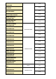
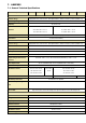
Screen 4.42: This alarm appears when the UPS is blocked for any reason. This condition blocks also
the rectifier.
Screen 4.43: After 3 times shutting down the rectifier for desaturation and retry, this alarm will
appear indicating rectifier blocked.
Screen 4.44: If an error in the initial rectifier ramp is detected during the PFC start up, this alarm
will appear blocking also the rectifier.
Screen 4.45: There is a command from the microprocessor to the DSP, with no response from the
rectifier module of the DSP. The rectifier will block.
Screen 4.46: After 4 times shutting down the rectifier because of (*) DSP Internal Error in the
rectifier module, this alarm will appear indicating rectifier blocked.
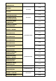
Screen 4.47: During the start up there is an input contactor test. If this test ends unsuccessfully
the rectifier will be blocked.
Screen 4.48: If the output voltage ramp doesn’t work properly during the inverter start up the
inverter will be blocked.
Screen 4.49: This alarm appears when there is an offset voltage higher than 8V, in any phase of the
inverter output voltage phase to neutral. Then the inverter will be blocked.
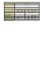
Screen 4.50: This alarm appears when the UPS is blocked for any reason. This condition blocks also
the inverter.
Screen 4.51: After 3 times shutting down the inverter for desaturation and retry, this alarm will
appear indicating inverter blocked.
Screen 4.52: There is a command from the microprocessor to the DSP, with no response from the
inverter module of the DSP. The inverter will block.
Screen 4.53: After 5 times shutting down the inverter because of (*) DSP Internal Error in the
inverter module, this alarm will appear indicating inverter blocked.
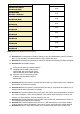
Screen 4.54: This alarm appears when the rectifier is blocked for some
reasons that can also blocks the UPS.
Screen 4.55: The alarm appears when the DSP doesn’t response to the microprocessor during the
initial procedure before the start up.
Screen 4.56: There is a command from the microprocessor to the DSP, with no response from the
UPS module of DSP. The UPS will block.
Screen 4.57: This alarm appears when the inverter is blocked for some reasons that can also blocks
the UPS.
Screen 4.58: There is an internal error in the communication channel between microprocessor and
DSP. This condition blocks the UPS.
Screen 4.59: This alarm appears when, in a parallel system, one UPS goes to battery mode. After
some period of time, the UPS will shut down.
Screen 4.60: When an overtemperature is detected by the PFC or inverter temperature sensors,
first the inverter will be turned off automatically after 1 minute time (alarm 4.31). If one minute later