
User manual

5-4. Bypass manual switch (MAINTENANCE)
5-4-1. Principle of operation.
The integrated manual bypass of the UPS is a very useful element, but undue use can have irreversible
consequences both for the UPS and for the loads connected to its output. It is therefore important to handle
it as described in the following paragraphs
5-4-2. Transfer to maintenance bypass
Procedure for passing from normal operation to maintenance bypass:
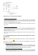
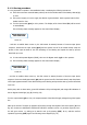
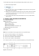
Shutdown the inverter. Through the keypad of the control panel ((3) from Fig. 26), go down to
“CONTROL & STATUS OF THE UNIT” submenu (screen 1.0), and then right only once. You will get to
screen 1.3, asking you to shutdown the unit by pressing (ESC). Do so, and then confirm operation
by pressing (ENT), see Fig 25.
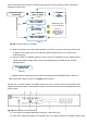
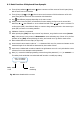
Remove the screws to that fixes the mechanical block (BL)
Remove the mechanical block (BL) of the manual bypass switch (Q5) and set it to «On» position.
Set the output switch (Q2) to «Off» position
Set the Battery Fuse Holder or battery switch (Q3) to «Off». Besides, in models with independent
battery pack/s also turn Battery Fuse Holder (Q8) of each pack to «Off».
In standard units, set the input switch (Q1a) to «Off» position.
In B units, set the input switch (Q1a) and static bypass switch (Q4) to «Off» position
The UPS is supplying output voltage directly from the mains through the manual bypass in units or from the
mains of the static line bypass in the version B units, through the manual bypass. The UPS is completely
shutdown and inactive.
5-4-3. Transfer to normal operation
Procedure for switching from maintenance bypass to normal operation:
In model with external battery cabinet, set fuse holder switch from battery cabinet (Q8) to «On»
position.
In standard units,, set the input switch (Q1a) to «On» position.
In B units, set the input switch (Q1a) and static bypass switch (Q4) to «On» position.
Set the output switch (Q2) to «On» position.
Set the manual bypass switch (Q5) to «Off» position and refit the mechanical block (BL) and the
screws (t2)
It is an essential requirement for safety to refit the mechanical block (BL), as this avoids
dangerous handling for the life of the UPS and the loads connected to it.
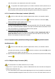
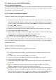
Start up the inverter. The start up operation will be done through the keypad of the control panel ((3)
from Fig. 26). Go down to «CONTROL & STATUS OF THE UNIT» submenu (screen 1.0), and then
right only once. You will get to screen 1.1, asking you to start the unit up by pressing (ENT). Do so,
and then confirm operation by pressing (ENT) again. See following screen diagram (Fig. 25).