
User manual

are protected through the UPS
5-2. Complete UPS shutdown
Shutdown the loads.
If the system has outgoing distribution protections, switch them «Off».
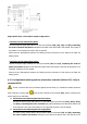
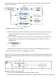
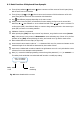
Shutdown the inverter. Through the keypad of the control panel ((3) from Fig. 26), go down to
“CONTROL & STATUS OF THE UNIT” submenu (screen 1.0), and then right only once. You will get to
screen 1.3, asking you to shutdown the unit by pressing (ESC). Do so, and then confirm operation
by pressing (ENT), see Fig 25.
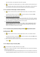
Turn the output switch (Q2) to «Off» position.
In standard units, set the input switch (Q1a) to «Off» position. In B units, set the input switch (Q1a)
and static bypass switch (Q4) to «Off» position.
Turn fuse holder switch from battery cabinet (Q8) and/or battery fuse holder switch or switch from
UPS (Q3), to «Off».
Cut the power supply of the UPS and the bypass with the cut-off or general switch of the header
board. The system will be completely deactivated.
Electrical discharge hazard. If after shutdown of the equipment, it is required to disconnect
the separate battery pack/s, wait several minutes (5 min. approx), till the electrolytic capacitors have
been discharged.
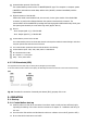
5-3. Emergency power off (EPO) operation
Emergency Power Off (EPO) is equivalent to a complete unit system halt.
All UPS converters are turned off (rectifier and inverter off)..
No output voltage is supplied to the loads.
That function can be commanded through 2-way connector (X50
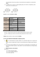
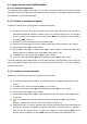
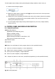
See table below for operation:
E.P.O. function
Activation
(perform System Halt)
Return to normal-mode
Terminals (X50).
Normally closed
circuit by means of
the provided cable
bridge (it allows an
external switch
(EPO)).
Remote button or switch has to
be opened permanently in
terminal strip (X50).
The equipment has to be shutdown and
deenergized completely (turn off all
switches), wait till DC bus is discharged (all
LEDs and LCD have to be turned off).
The equipment has to be started up
according to section “5.1.2. Start up
procedure”.
Table.4. Emergency Power Off (EPO) operation