
User manual
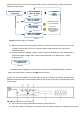

for connecting the UPS with any machine or devices that has this standard bus (connector DB9
(X32))
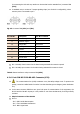
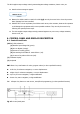
In standard units, it consists of 5 output signaling relays (one of which is configurable), whose
common point is connected to pin 5.
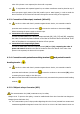
Fig. 23. Connector DB9 (X31) and (X32).
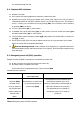
Pin-out No.
Description
N.C.-N.O. Position
1
Shutdown signal +
-
2
Shutdown signal –
-
3
Configurable
Not connect
4
Discharge - Mains failure
N.C.
5
Common
-
6
Equipment in Bypass
N.O.
7
Low battery
N.O.
8
General alarm
N.O.
9
Discharge - Mains failure
N.O.
N.C.: Normally closed contact. On the alarm having activated the contact is opened
N.O.: Normally open contact. On the alarm having activated the contact is closed
Table3. Alarms interface to relays connector DB9 (X32)
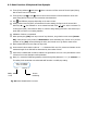
4-3-6. Port COM RS-232 & RS-485. Connector (X32).
The communications line (COM) constitutes a very low safety voltage circuit. To preserve the
quality, it must be installed aside from other lines that have dangerous voltages (power distribution
line).
In the same connector DB9 there are given both ports of communication of the equipment, the
RS-232 and the RS-485. Anyway it is not possible to use them simultaneously for being mutually
exclusive.
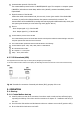
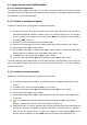
Physical structure of the RS-232
Pin-out
- Pin 2. RXD. Serial data reception.
- Pin 3. TXD. Serial data transmission.
- Pin 5. GND. Signal mass