
User manual

Single phase input / three phase output configuration.
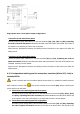
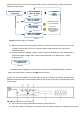
Connection to the mains three phase:
Connect the power supply cables N-R-S-T to the input terminals (X4), (X1), (X2) and (X3), respecting
the order of neutral and phases indicated on the label of the device and in this manual. If the order of
the phases is not respected, the device will not operate.
When there are discrepancies between the labeling and the instructions of this manual, the label will
always prevail.
Connection to the mains single phase:
Connect the power supply cables R-N to the input terminals (X1) and (X4), respecting the order of
phase and neutral indicated on the label of the device and in this manual. If the order of the phases is not
respected, the device will not operate.
When there are discrepancies between the labeling and the instructions of this manual, the label will
always prevail.
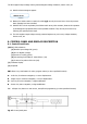
4-3-2. Independent static bypass line connection, terminals (X14 to X17). Only in
versions UPS-B.
As this is a device with class I protection against electric shocks, it is essential to install a protective
earth conductor (connect earth ( ).Connect the conductor to the terminal (X5), before connecting the
power supply to the UPS input.
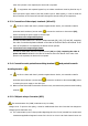
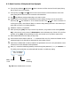
Connection to the static bypass line three phase:
Connect the power supply cables N-R-S-T to the static bypass line terminals (X17), (X14), (X15)
and (X16), respecting the order of neutral and phases indicated on the label of the device and
in this manual. If the order of the phases is not respected, the device will not operate.
Connection to the static bypass line single phase:
Connect the power supply cables R-N to the static bypass line terminals (X1) and (X4), respecting
the order of phase and neutral indicated on the label of the device and in this manual. If the