
User manual
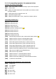
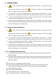

(a) Rectifier Input Voltage OK led (green).
(b) Output voltage unit from the Bypass led (orange).
(c) Inverter is working led (green).
(d) Unit working from batteries -mains failure- led (red).
(e) General alarm. In case of any alarm of the unit led (red).
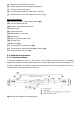
Other abbreviations:
(BL) Mechanical block for manual bypass switch (Q5).
(CL) Lock for cabinet front door.
(PB) Levelers and immobilizing elements.
(PC) Control panel.
(PF) Cabinet front door.
(PR) Cable stuffers or wire cones.
(RD) Scroll wheel.
(SL) Slot for optional intelligent card.
(TB) Terminal cover.
(TS) Slot cover (SL).
(t
1
) Screws fixing for terminals cover (TB).
(t
2
) Screws fixing for mechanical block (BL) for switch (Q5).
(t
3
) Screws fixing for slot cover (TS).
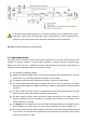
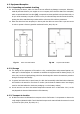
3-2. Definition and structure
3-2-1. Structural Scheme
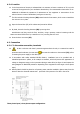
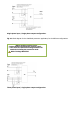
In single line diagrams of figures 17 and 18 show, as an example, the basic structure of a standard
equipment and another one with separate bypass line, for a three phase input and output configuration. For
any other configuration, the quantity of cables and terminals at the input, output and bypass will only vary;
internal structure of the equipment will never do it.
Fig..17. UPS block diagram with operating flows.