
User manual
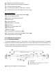
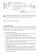
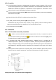

3-1-2. Corresponding legends to the equipment views
Protection and handling elements (Q*):
(Q1a) Input circuit breaker or switch according to power of the equipment.
(Q2) Output switch.
(Q3) Battery fuse holder switch with 3 fuses (models up to 40 kVA) or switch
(for higher models).
(Q4) Static bypass (Only in optional version -B).
(Q5) Maintenance bypass switch.
(Q8) Battery fuse holder switch 3 fuses, located in the battery cabinet.
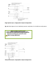
Connecting elements (X*):
(X1) Phase input terminal R.
(X2) Phase input terminal S.
(X3) Phase input terminal T.
(X4) Neutral input terminal N.
(X5) Main protection earthing terminal ( ).
(X6) Phase output terminal U.
(X7) Phase output terminal V.
(X8) Phase output terminal W.
(X9) Neutral output terminal N.
(X10) Earth bonding terminal for load or loads and/or battery cabinet ( ).
(X11) Batteries terminal +(Only for external battery model).
(X12) Batteries terminal –(Only for external battery model).
(X14) Phase static bypass terminal R (Only in optional version -B).
(X15) Phase static bypass terminal S (Only in optional version -B).
(X16) Phase static bypass terminal T (Only in optional version -B).
(X17) Neutral static bypass terminal N (Only in optional version -B).
(X23) Batteries terminal N (middle tap, Only for external battery model).
(X31) DB9 connector COM RS-232 and RS-485 ports.
(X32) DB9 connector relay interface.
(X47) Batteries terminal + of external batteries cabinet.
(X48) Batteries terminal – of external batteries cabinet.
(X49) Batteries terminal N (middle tap) of external batteries cabinet.
(X50) Terminals for external EPO.
Keyboard and optical indications control panel (PC):
(LCD) Display LCD.
(ENT) Key «ENTER».
(ESC) Key «ESC».
(
)
Key move up
.
(
)
Key move down.
(
)
Key move to right.
(
)
Key move to left.