HI-TECH PRO UNINTERRUPTIBLE POWER SUPPLY USER MANUAL info@tuncmatik.com / www.tuncmatik.
GENERAL INDEX 1. INTRODUCTION 1-1. GRATEFULNESS LETTER 1-2. USİNG THİS MANUAL 1-2-1. Used Symbols 1-2-2. For More Information & Help 2. QUALITY AND STANDARD GUARANTEE 2-1. STANDARD 2-2. ENVİRONMENT 3. PRESENTATION 3-1. VİEWS 3-1-1. Views of the equipment 3-1-2. Corresponding legends to the equipment views 3-2. DEFİNİTİON AND STRUCTURE 3-2-1. Structural Scheme 3-3. OPERATİNG PRİNCİPLE 3-3-1. Normal operation, () 3-3-2. Operation with mains failure, () 3-3-3. Operation with inverter not active, () 3-3-4.
5-1-2. Start up procedure 5-2. COMPLETE UPS SHUTDOWN 5-3. EMERGENCY POWER OFF (EPO) OPERATİON 5-4. BYPASS MANUAL SWİTCH (MAINTENANCE) 5-4-1. Principle of operation 5-4-2. Transfer to maintenance bypass 5-4-3. Transfer to normal operation 6. CONTROL PANEL AND DISPLAY DESCRIPTION 6-1. CONTROL PANEL PARTS 6-2. BASİC FUNCTİONS OF KEYBOARD FROM SYNOPTİC 6-2-1. Messages menus and classification in submenus 6-3. SCREEN DESCRİPTİON 6-3-1. Main level (screen menu 0.0). See Fig. 30 6-3-2.
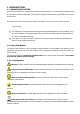
1. INTRODUCTION 1-1. GRATEFULNESS LETTER We would like to thank you in advance for the trust you have placed in us by purchasing this product. Read this instruction manual carefully before starting up the equipment and keep it for any possible future consult that can arise. We remain at you entire disposal for any further information or any query you should wish to make. Yours sincerely The equipment here described can cause important physical damages due to wrong handling.
1-2-2. For More Information & Help For more information and/or help of the version of your specific unit, request it to our Service and Technical Support. 2. QUALITY AND STANDARD GUARANTEE 2-1. Standard The UPS series product is designed, manufactured and commercialized in accordance with the standard EN ISO 9001 of Quality Management Systems.
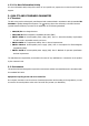
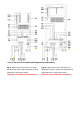
3. PRESENTATION 3-1. Views 3-1-1. Views of the equipment Fig. 2. Cabinet front view for UPS up to 20kVA Fig. 3. Cabinet front view for UPS from 30 to with front door closed. 80kVA with front door closed. Fig. 4.
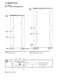
* Only in optional version UPS-B (Static Bypass line independent). Fig. 5. Cabinet front view for UPS up to 20kVA Fig. 6. Cabinet front view for UPS up to 30 to with front door opened and configuration of three 80kVA with front door opened and configuration of phase input / three phase output. three phase input three phase output.
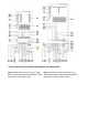
* Only in optional version UPS-B (Static Bypass line independent). Fig. 7. Cabinet front view for UPS up to 20kVA Fig. 8. Cabinet front view for UPS from 30 to with front door opened and configuration of three 80kVA with front door opened and configuration of phase input / single phase output. three phase input / single phase output.
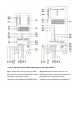
* Only in optional version UPS-B (Static Bypass line independent). Fig. 9. Cabinet front view for UPS up to 20kVA Fig. 10. Cabinet front view for UPS from 30 to with front door opened and configuration of single 80kVA with front door opened and configuration of phase input / single phase output. single phase input / single phase output.
* Only in optional version UPS-B (Static Bypass line independent). Fig. 11. Cabinet front view for UPS up to 20kVA Fig. 12. Cabinet front view for UPS from 30 to with front door opened and configuration of single 80kVA with front door opened and configuration phase input / three phase output. of single phase input / three phase output.
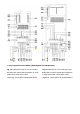
3-1-2. Corresponding legends to the equipment views Protection and handling elements (Q*): (Q1a) Input circuit breaker or switch according to power of the equipment. (Q2) Output switch. (Q3) Battery fuse holder switch with 3 fuses (models up to 40 kVA) or switch (for higher models). (Q4) Static bypass (Only in optional version -B). (Q5) Maintenance bypass switch. (Q8) Battery fuse holder switch 3 fuses, located in the battery cabinet. Connecting elements (X*): (X1) Phase input terminal R.
(a) Rectifier Input Voltage OK led (green). (b) Output voltage unit from the Bypass led (orange). (c) Inverter is working led (green). (d) Unit working from batteries -mains failure- led (red). (e) General alarm. In case of any alarm of the unit led (red). Other abbreviations: (BL) Mechanical block for manual bypass switch (Q5). (CL) Lock for cabinet front door. (PB) Levelers and immobilizing elements. (PC) Control panel. (PF) Cabinet front door. (PR) Cable stuffers or wire cones.
In equipments with separate bypass line, an isolation transformer must be placed at any of both input power supply mains of the UPS (rectifier input or static bypass), in order to avoid the direct connection of the neutral of both mains through the internal wiring of the equipment. Fig. 18. UPS-B block diagram with operating flows. 3-3.
3-3-1. Normal operation, () With the mains present, the rectifier transforms the AC input voltage into DC raising the DC voltage to a suitable level for supplying the inverter and to charge the batteries. The inverter deals with transforming the voltage of the DC bus into AC, providing a sine wave alternating output, stabilized in voltage and frequency to supply the loads connected to the output (figures 17 and 18). 3-3-2.
4. INSTALLATION As this is a device with class I protection against electric shocks, it is essential to install a protective earth conductor (connect earth ( )). Connect the conductor to the terminal (X5), before connecting the power supply to the UPS input. All connections in the device, including those for control (interface, remote control, ...), will be performed with the switches at rest and without any mains present (UPS power line cut off «Off»).
Never manipulate with your hands or through conducting objects, do not short the battery terminal block or the battery enclosure. Never short the battery terminals as it involves a high risk. It involves the detriment of the equipment and batteries Avoid mechanical efforts and impacts Do not open or mutilate the battery. Released electrolyte is harmful to the skin and eyes. Do not dispose of batteries in a fire. The batteries may explode.
Maximum input and bypass current, nominal output current (A) Model Power (kVA) 3x380 V Input Output 3x400 V 3x415 V Bypass Input Output Bypass Input Output Bypass UPS-15 15 22 23 - 21 22 - 20 21 - UPS-20 20 30 30 - 28 29 - 28 28 - UPS-30 30 44 45 - 43 43 - 40 41 - UPS-40 40 59 61 - 57 58 - 53 55 - UPS-50 50 74 76 - 71 72 - 67 68 - UPS-60 60 89 91 - 85 87 - 80 82 - UPS-80 80 118 122 - 113 116 - 107 110 - UPS-15-B 15 2
4-2. Equipment Reception 4-2-1. Unpacking and content checking On receiving the device, make sure that it has not suffered any damage in transport. Otherwise, make all pertinent claims to your supplier or to our company. Also check the data in the nameplate, which is sticked inside the front door (PF), corresponds to those specified in the purchase order, to do it, it will be necessary to unpack it.
4-2-4. Location In the Instructions of Security is indicated that it is necessary to leave a minimum of 25 cm in the contour of the equipment for your ventilation. Nevertheless, one recommends to leave other 75 cm. additional to facilitate the operations of maintenance of the equipment or interventions of the technical service in case of breakdown (see figures 19 and 20). The UPS includes 2 leveling elements (PB) located near the front castors, which serve to immobilize the unit once it is in place.
Single phase input / single phase output configuration. Fig. 21. Block diagram for the «Backfeed protection» application, for the different configurations. Before working on this circuit. - Isolate Uninterruptible Power System (UPS). - Then check for Hazardous Voltage between all terminals including the protective earth. Risk of Voltage Backfeed. Three phase input / single phase output configuration.
Single phase input / three phase output configuration. Connection to the mains three phase: Connect the power supply cables N-R-S-T to the input terminals (X4), (X1), (X2) and (X3), respecting the order of neutral and phases indicated on the label of the device and in this manual. If the order of the phases is not respected, the device will not operate. When there are discrepancies between the labeling and the instructions of this manual, the label will always prevail.
order of the phases is not respected, the device will not operate. In equipments with separate bypass line, an isolation transformer must be placed at any of both input power supply mains of the UPS (rectifier input or static bypass), in order to avoid the direct connection of the neutral of both mains through the internal wiring of the equipment.. 4-3-3.
for connecting the UPS with any machine or devices that has this standard bus (connector DB9 (X32)) In standard units, it consists of 5 output signaling relays (one of which is configurable), whose common point is connected to pin 5. Fig. 23. Connector DB9 (X31) and (X32). Pin-out No. Description N.C.-N.O. Position 1 Shutdown signal + - 2 Shutdown signal – - 3 Configurable Not connect 4 Discharge - Mains failure N.C. 5 Common - 6 Equipment in Bypass N.O. 7 Low battery N.O.
Communication protocol of the RS-232. The communication protocol used is of «MASTER/SLAVE» type. The computer or computer system («MASTER») asks about a certain data, and the UPS («SLAVE») answers immediately with the required data. Physical structure of the RS-485. Unlike other serial communication links, this uses only 2 wires (pins 4 and 9 of the female DB9 connector) to perform the dialogue between the systems connected to the network.
5-1-2. Start up procedure. It is very important to operate in the established order, considering the following instructions. If the UPS connects to external battery cabinet, set the fuse holder switch of the battery cabinet(Q8) to «On» If the power supply you use to supply the UPS has a general switch. Set the general switch of the header board to «On». Turn the input switch (Q1a) to «On» position.
After a few seconds, the UPS will be running (rectifier working, inverter working), and the output will be supplied from the inverter. CONTROL & STATUS OF THE UNIT screen 1.0 screen 1.1 (ESC) UPS ON STAND-BY TO START (ENT) TO CONFIRM TO CANCEL (ENT) (ESC) screen 1.2 UPS Start UP «screen 1.1» is now replaced by «screen 1.3» UPS Shutdown (on Bypass) «screen 1.3» is now replaced by «screen 1.1». screen 1.3 TO CONFIRM TO CANCEL screen 1.
are protected through the UPS 5-2. Complete UPS shutdown Shutdown the loads. If the system has outgoing distribution protections, switch them «Off». Shutdown the inverter. Through the keypad of the control panel ((3) from Fig. 26), go down to “CONTROL & STATUS OF THE UNIT” submenu (screen 1.0), and then right only once. You will get to screen 1.3, asking you to shutdown the unit by pressing (ESC). Do so, and then confirm operation by pressing (ENT), see Fig 25.
5-4. Bypass manual switch (MAINTENANCE) 5-4-1. Principle of operation. The integrated manual bypass of the UPS is a very useful element, but undue use can have irreversible consequences both for the UPS and for the loads connected to its output. It is therefore important to handle it as described in the following paragraphs 5-4-2. Transfer to maintenance bypass Procedure for passing from normal operation to maintenance bypass: Shutdown the inverter. Through the keypad of the control panel ((3) from Fig.
The UPS supplies output voltage entirely protected against voltage variations, electric noise, etc. Wait for alarm message to appear: BATT. SWITCH OPEN SWITCH IT ON screen* Battery fuse holder switch or switch from UPS (Q3) can only be turned «On» when the previous alarm message has been cancelled. DO NOT TRY to close any battery fuse holder switch at any other moment, because this operation could damage the equipment and/or cause possible accidents.
6-2. Basic Functions Of Keyboard From Synoptic Through keys advance () and return (), there is access to all the menus of the LCD panel, being able to move from one to another. Through keys right () or left (), there is access to the screens of all the submenus of the LCD panel, being able to move from one to another with themselves. Key ( ), has different purposes depending on the menu we are: Setting values. Press key (ENT) to activate the function setting, the figures in the screen blink.
6-2-1. Messages menus and classification in submenus Use () and () keys to choose between different menus (0.0, 1.0, …, 7.0). Use () and ()keys to move inside submenu screens.
- «Dischar.» Mains failure. UPS running on back-up mode (rectifier stopped, inverter running). Origin of the output: - «OFF» No voltage supplied at the output (either EPO pressed, or severe problem on the unit). - «Invert» Inverter voltage is supplied at the output. Loads are protected -«Bypass» Bypass voltage is supplied at the output.
6-3-3. ‘‘PARAMETERS’’ level (screen menu 3.0). See Fig. 33. Screen 3.1: In the first row you can program the time “hh:mm:ss” (hours/minutes/seconds) and in the second row you can program the date “dd/mm/yy” (day/month/year). Screen 3.2: In the first row you can select the display language between the following options: “Español” “English” “Francais” In the second row you can program the Modbus Address. The range of addresses goes from 1 to 247. Screen 3.
‘’TUE”: Tuesday ‘’WED”:Wednesday ‘’THU”: Thursday ‘’FRI”: Friday ‘’SAT”: Saturday ‘’SUN”: Sunday Screen 3.17: This screen appears independently on the last screen, but it only have sense to be programmed if the automatic battery test is enabled. In this screen you can program the time “hh:mm” (hours/minutes) in 24h format. Screen 3.18: This screen appears independently on the last screen, but it only have sense to be programmed if the automatic battery test runs monthly or yearly.
Screen 4.1: This alarm indicates that the rectifier is overloaded. The rectifier overload appears when the input current of any phase is greater than the following ratio: Iin-ovl = 0,326 x Pout / Vout_p-n - Iin-ovl is Overload Input Current (A) - Pout is Rated Output Apparent Power (VA) - Vout_p-n is Rated Output Voltage phase-to-neutral (V) Screen 4.2: This alarm indicates that the inverter is overloaded.
Screen 4.12: This is an alarm for parallel systems. It appears when some UPS of the parallel system block because the maintenance bypass switch of any unit is switched ON. Screen 4.13: This alarm indicates that the CAN BUS #1 fails. This communication channel is used for remote control. Screen 4.14: This alarm indicates that the CAN BUS #2 fails. This channel is used for data communication between UPS, in a parallel system. Screen 4.
END OF BATTERY 4.15 LIFE ALARM BATT. TEMPERATURE 4.16 TOO HIGH BATTERY TEST 4.17 NOT SUCCEEDED BAT.DISCONNECTION 4.18 SHUTDOWN & RESTART MAINS PHASE ROT. 4.19 UPS START INH. BYPASS PHASE ROT. 4.20 UPS START INH. INP. VOLTA. WRONG 4.21 RECTIFIER STOP RECTIFIER DESATS. RECTIFIER STOP DSP INTERN. ERROR 4.22 RECTIFIER STOPS 4.23 RECTIFIER STOP INPUT PHASE ROT. 4.24 RECTIFIER STOP INVERTER DESATS. 4.25 INVERTER STOP INVERTER OVERLOAD 4.26 INVERTER STOP SHUTDOWN COMMAND 4.
BYPASS PHASE ROT. 4.35 INVERTER STOP DSP INTERN. ERROR UPS STOP LOW BATTERY 4.36 UPS STOPS 4.37 UPS STOP EMERGE. POWER OFF 4.38 NO OUTPUT VOLTAGE OUT SHORT-CIRCUIT BYP STOPS NO OUTPUT VOLTAGE DSP INTERN. ERROR 4.40 UPS BLOCK ALL DC BUS VOLT WRONG 4.41 RECTIFIER BLOCK RECTIFIER BLOCKED 4.42 BLK.UPS -> BLK.REC RECTIFIER DESATS. 4.43 RECTIFIER BLOCK VOLTAGE RAMP ERR. RECTIFIER BLOCK RECTIFIER BLOCKS INTERN.EXE. ERROR DSP INTERN. ERROR 4.46 RECTIFIER BLOCK CONTACTOR T. FAIL 4.
UPS BLOCK (DSP) INTERN.EXE. ERROR UPS BLOCK (DSP) UPS BLOCKED BLK.INV -> BLK.UPS INTERN.COM. ERROR UPS BLOCK (DSP) PARAL. SYS. DISC. UPS BLOCK UPS OVERTEMPERAT. UPS BLOCK RECTIFIER OVERLO. UPS BLOCK INVERTER DESATS. UPS BLOCK DSP INTERN. ERROR UPS BLOCK PFC & INV BLOCK. UPS BLOCK 4.56 4.57 4.58 4.59 4.60 4.61 4.62 4.63 4.64 Table .6 Alarm list displayed in the LCD panel. Screen 4.
rectifier is tried to be turned ON, an input phase rotation alarm appears shutting down the rectifier. Screen 4.25: This alarm appears when any IGBT in the inverter side, desaturates the number of times programmed by display (200 by default). Screen 4.26: When the inverter output is overloaded, depending on the level of this overload, the inverter will be shut down after some time according to the UPS overload curve and this alarm will appear. Screen 4.
Positive DC bus voltage over 450V. Positive DC bus voltage less than 325V. Negative DC bus voltage over –450V (absolute value). Screen 4.42: This alarm appears when the UPS is blocked for any reason. This condition blocks also the rectifier. Screen 4.43: After 3 times shutting down the rectifier for desaturation and retry, this alarm will appear indicating rectifier blocked. Screen 4.
the overtemperature is still detected, the UPS will be completely blocked (rectifier also shut-down) and the alarm appears. Screen 4.61: When the rectifier is overloaded, depending on the level of this overload, the inverter will be shut down after some time according to the rectifier overload curve (alarm 4.32). If this overload is still present with the inverter switched off, the UPS will be completely blocked (rectifier also shut-down) after 30’’, appearing this alarm message. Screen 4.
hh: hour of deleted alarm mm: minutes of deleted alarm ss: seconds of deleted alarm dd: day of deleted alarm mm: month of deleted alarm yy: year of deleted alarm Screen 5.5: This is a screen for technical service, to know the state of the different parts of the UPS at the moment the registered alarm was activated. DATA LOGGER () () HOURS INVERTER ON 145 screen 5.0 () () 00) INVERTER OVERLOAD screen 5.1 () () R: RUN I:RUN P: INIT U:UPS RUN FLGS:04 screen 5.
6-3-7. Rated values screens (screen menu 7.0). See Fig. 37 RATED VALUES (*1 ) () () screen 7.0 I.Voltage=230V B. Voltage=230V (*1) () () screen 7.1 DC Bus Volt=425V Out. Curre.=86.9A (*1) screen 7.4 I.V Min. Marg=22% I.V Max. Marg=15% (*1) () () Byp. Min. Marg=17% Byp. Max. Marg=12% (*1) screen 7.2 Inv Voltage=230V Out Voltage=230V (*1) () () () () screen 7.5 screen 7.3 Batt. Charging Curr. 3.6A (*1) screen 7.6 Fig..37. Screen 7.0 «Rated values» and its submenus.
7. ANNEXES 7-1. General Technical Specifications Nominal power (kVA) 10 15 20 30 40 60 80 Input Nominal voltage Single phase 220 V, 230 V or 240 V. Three phase 3x380 V, 3x400 V or 3x415 V (4 wires: 3 phases + N). Input voltage margin + 15% / –20%. Frequency 50 / 60 Hz ±5 %. Input current total harmonic 100 % load: THD-i < 1.5 %. 100 % load: THD-i < 1.0 %. distortion 50 % load: THD-i < 2.5 %. 50 % load: THD-i < 2.0 %. 10 % load: THD-i < 6.0 %. 10 % load: THD-i < 5.0 %.
MANUAL BYPASS (maintenance) Type Voltage Without interruption. Single phase 220 V, 230 V or 240 V. Three phase 3x380 V, 3x400 V or 3x415 V (4 wires: 3 phases + N). Frequency 50 / 60 Hz. GENERAL Overall efficiency 91,0 % 91,5 % 92,0 % 93,0 % 93,5 % 94,0 % 95,0 % Dimensions & weight (cabinet ups) Depth x Width x Height (mm) / 700 x 450 x 1100 / YES. 805 x 590 x 1320 / YES.