
User's Manual

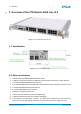
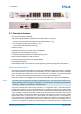
Table Of Contents
- Front Cover
- Table of Contents
- List of Tables
- List of Figures
- Disclaimer
- Limited Rights Notice
- 1 Introduction
- 2 Overview
- 3 Functional description
- 4 Getting started
- 5 State machine
- 6 Creating a switch configuration
- 7 Diagnosis
- 8 Troubleshooting
- Appendix A List of Built-In Self-Tests
- Appendix B Serial terminal output at start-up
- Glossary
- References
- Index

2. OVERVIEW
≡
2 Overview of the TTE-Switch A664 Lab v2.0
Figure 1: The TTE-Switch A664 Lab v2.0
2.1 Identification
Figure 2: Product identification label
2.2 External interfaces
1. 4 x Status LEDs (POWER/STATUS/SYNC/DEF. CONF)
2. 1 x DB-25S configuration interface for diagnosis and maintenance and access to switch discretes
3. 1 x 10/100/1000 Mbit/s MIRROR port for mirroring
4. 2 x 10/100/1000 Mbit/s Ethernet ports (PORT1 and PORT2) that can be used either via SFP or RJ45
5. 4 x 10/100/1000 Mbit/s Ethernet ports via RJ45
6. 18 x 10/100 Mbit/s Ethernet ports via RJ45
7. 1 x Ethernet Link/Activity LED per port
8. 1 x JTAG connector for factory testing and programming
9. 1 x RS-232 serial interface that can be used for debugging
10. 1 x IEC 60320-1 C13 type power connector. The switch has an electrical fuse that protects the
external power rail so that a failing switch does not cause the system power supply rail to fail.
© TTTech Computertechnik AG 2020. All rights reserved.
Confidential and Proprietary Information
7
Document Number:
D-A664Lab-G-05-001