
User's Manual
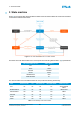

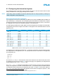
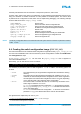
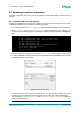
Table Of Contents
- Front Cover
- Table of Contents
- List of Tables
- List of Figures
- Disclaimer
- Limited Rights Notice
- 1 Introduction
- 2 Overview
- 3 Functional description
- 4 Getting started
- 5 State machine
- 6 Creating a switch configuration
- 7 Diagnosis
- 8 Troubleshooting
- Appendix A List of Built-In Self-Tests
- Appendix B Serial terminal output at start-up
- Glossary
- References
- Index

6. CREATING A SWITCH CONFIGURATION
6.3 Configuring the internal end system
The management CPU of the switch uses an internal end system to send and receive frames for data
loading via ARINC 615A, ICMP (ping) and diagnostics via SNMP.
NOTE
Data loading, ICMP and SNMP via best-effort (Ethernet) traffic are always possible by selecting the
default configuration via pin programming.
Rate-constrained management configuration
If a management service such as data loading via ARINC 615A, ICMP, and SNMP shall be available via
rate-constrained (i.e., critical) traffic, the corresponding virtual links between the maintenance computer,
the switch and the switch-internal end system need to be defined and configured correctly. The minimum
VL configuration from a port to the internal end system is 4 user-defined VLs.
For data loading via ARINC 615A, ICMP, SNMP, and other management functionalities via critical traffic,
the application ports must be configured. See Table 8 on this page for a list of the default values for internal
application ports.
Name Port Type
1
Port
2
Partition
2
VL_ID Protocol
#ICMP_TX IPSAP 8 1 200 1
#ICMP_RX IPSAP 8 1 100 1
#SNMP_TX UDPSAP 4 5 203 161
#SNMP_RX UDPSAP 32 5 103 161
#A615_MAIN_TX UDPSAP 1 3 202 59
#A615_MAIN_RX UDPSAP 24 3 102 59
#A615_STATUS_TX UDPSAP 2 4 202 1022
#A615_STATUS_RX UDPSAP 25 4 102 1022
#A615_FIND_TX UDPSAP 0 2 201 1001
#A615_FIND_RX UDPSAP 16 2 101 1001
Table 8: Default values for internal application ports for critical and best-effort traffic
The application port configuration file utilizes the .ini file format. Each section in the file represents exactly
one configuration for one application port. The example below shows a valid section in the application
port configuration file:
[#ICMP_RX]
dir = rx
port = 8
part = 1
The values for port and part must match the values of the header file of the internal end system, which
is created by the TTE-Tools (see Section 6.1 on the previous page). The application port configuration file
must be declared in the example_configs.ini file.
The example_configs.ini file defines configurations grouped in sections, with each section representing
exactly one configuration. The order of sections listed in the .ini file implicitly shows the relation between
a configuration position selected by pin programming (see Table 3 on page 13) and a section defined in
the .ini file. This means that the binary files defined in the first section correspond to position 1, while
1. The port type is MACRAW in the case of best-effort traffic.
2. In the case of best-effort traffic, port and partition cannot be changed and are set to 0.
© TTTech Computertechnik AG 2020. All rights reserved.
Confidential and Proprietary Information
25
Document Number:
D-A664Lab-G-05-001