
User's Manual
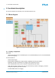
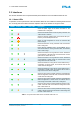
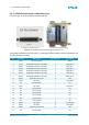
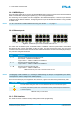
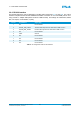
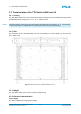
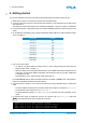

Table Of Contents
- Front Cover
- Table of Contents
- List of Tables
- List of Figures
- Disclaimer
- Limited Rights Notice
- 1 Introduction
- 2 Overview
- 3 Functional description
- 4 Getting started
- 5 State machine
- 6 Creating a switch configuration
- 7 Diagnosis
- 8 Troubleshooting
- Appendix A List of Built-In Self-Tests
- Appendix B Serial terminal output at start-up
- Glossary
- References
- Index

4. GETTING STARTED
≡
4 Getting started
This section describes the sequence of steps to get started with the TTE-Switch A664 Lab v2.0.
1. Make sure the switch is connected to a power outlet and switched off.
2. Connect an RS-232 connector to the RS-232 serial interface on the back panel of the switch (see
also Appendix B).
The settings for serial communication are: 19200 baud, 8 data bits, 1 stop bit, no parity, no handshake.
3. Connect the DB-25P configuration plug to the DB-25S CONFIG interface on the front panel of the
switch.
4. On the DB-25P configuration plug, use the following dip switch positions to load the default configu-
ration of Position 0:
Dip Switch Position
Con_Sel_0 OFF
Con_Sel_1 ON
Con_Sel_2 ON
Con_Sel_3 ON
Con_Sel_4 ON
Con_Sel_5 ON
Shop-Mode OFF
Maintenance OFF
Grnd-Mode ON
5. Turn on the power switch.
• On start-up, all status LEDs are briefly turned on, which changes during the switch start-up
sequence (see Table 1 on page 11).
• When the switch has successfully finished start-up, the POWER LED and the STATUS LED are
solid green. As the switch default configuration was selected for start-up, the DEF. CONF LED
is solid green as well.
• See Appendix B for the serial terminal output during start-up.
In the Operational state the switch provides information via SNMP. In SHOP mode, it is possible to
retrieve more detailed information via serial terminal.
6. Connect a host PC directly to one of the 24 front-panel ports using a standard Cat5 or Cat5e patch
cable.
• Set the IP address of the host PC to the same subnet as the switch, for example to 10.10.10.20.
• Set the subnet mask of the host PC to 255.255.255.0.
• Set the transmission speed to 100 Mbps Full Duplex and make sure auto-negotiation is acti-
vated.
7. To verify that the switch is operational, open the CLI window, type ping 10.10.10.10 and press
Enter . If no data packet was lost, the ping was successful.
Pinging 10.10.10.10 with 32 bytes of data:
Reply from 10.10.10.10: bytes =32 time=12ms TTL=128
Reply from 10.10.10.10: bytes =32 time=9ms TTL=128
Reply from 10.10.10.10: bytes =32 time=7ms TTL=128
© TTTech Computertechnik AG 2020. All rights reserved.
Confidential and Proprietary Information
18
Document Number:
D-A664Lab-G-05-001