
User's Manual
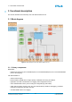
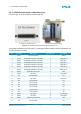
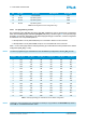
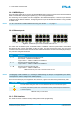
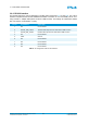
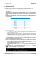
Table Of Contents
- Front Cover
- Table of Contents
- List of Tables
- List of Figures
- Disclaimer
- Limited Rights Notice
- 1 Introduction
- 2 Overview
- 3 Functional description
- 4 Getting started
- 5 State machine
- 6 Creating a switch configuration
- 7 Diagnosis
- 8 Troubleshooting
- Appendix A List of Built-In Self-Tests
- Appendix B Serial terminal output at start-up
- Glossary
- References
- Index

3. FUNCTIONAL DESCRIPTION
3.2.6 RS-232 interface
The RS-232 interface is used for debugging in SHOP mode (see Section 5.6 on page 22). The control
interface complies with the RS-232 standard and enables connection to one of the COM ports of a PC
using a serial 1:1 adapter cable (DB-9 connector to DB-9 socket). The settings are 19200 baud, 8 data
bits, one stop bit, no handshake, no parity.
Pin No. Signal Name Signal Type
1 NC Not connected
2 RS232_TXD_D-SUB Transmit data output from the TTE-Switch A664 Lab v2.0
3 RS232_RXD_D-SUB Receive data input from the TTE-Switch A664 Lab v2.0
4 NC Not connected
5 GND Ground
6 NC Not connected
7 NC Not connected
8 NC Not connected
9 NC Not connected
Table 6: Pin assignment of the RS-232 interface
© TTTech Computertechnik AG 2020. All rights reserved.
Confidential and Proprietary Information
15
Document Number:
D-A664Lab-G-05-001