
User's Manual
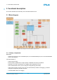
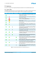


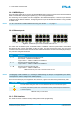

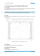

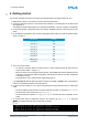

Table Of Contents
- Front Cover
- Table of Contents
- List of Tables
- List of Figures
- Disclaimer
- Limited Rights Notice
- 1 Introduction
- 2 Overview
- 3 Functional description
- 4 Getting started
- 5 State machine
- 6 Creating a switch configuration
- 7 Diagnosis
- 8 Troubleshooting
- Appendix A List of Built-In Self-Tests
- Appendix B Serial terminal output at start-up
- Glossary
- References
- Index

3. FUNCTIONAL DESCRIPTION
3.2.3 MIRROR port
The TTE-Switch A664 Lab v2.0 has a 10/100/1000 Mbit/s mirror port that can be used to forward selected
traffic to a dedicated monitoring end system (e.g. a PC running Wireshark).
For monitoring, an end system must be configured in the network description, or the mirror port must be
configured via the RS-232 interface. Configuring the mirror port via the RS-232 interface is only possible
in SHOP mode.
NOTE
For CLI commands to enable hardware mirroring, see Section 7.5.3 on page 33.
3.2.4 Ethernet ports
Figure 7: The Ethernet ports of the TTE-Switch A664 Lab v2.0
The switch has 24 Ethernet ports, numbered PORT1 to PORT24. Ethernet ports PORT1 and PORT2
are special as they can be used either via SFP or RJ45. For each of these two ports, only one of the
connectors can be used at a time as both the SFP and RJ45 interface connect to the same physical layer.
The ports are configured as follows:
Port Description
1 … 2 General-purpose SFP and RJ45 Ethernet ports:
fiber medium – 100Base-FX/1000Base-X
copper medium – 10Base-T/100Base-TX/1000Base-T
3 … 6 General-purpose RJ45 Ethernet ports:
copper medium – 10Base-T/100Base-TX/1000Base-T
7 … 24 General-purpose RJ45 Ethernet ports:
copper medium – 10Base-T/100Base-TX
Table 4: Ethernet ports of the TTE-Switch A664 Lab v2.0
NOTE
Hot-plugging of SFP modules (i.e. inserting a module during run-time) is not supported by the switch
and requires a reset to configure the module properly.
There are two LEDs per port integrated in the connector, a green Link LED and a yellow Activity LED.
Port LED Description
The Link LED is solid green when a link is established with the connected end system.
The Activity LED flashes yellow when communication activity is detected (frame transmission
or frame reception).
Table 5: RJ45 port LED status
3.2.5 JTAG interface
The JTAG connector is used for factory testing and firmware programming.
© TTTech Computertechnik AG 2020. All rights reserved.
Confidential and Proprietary Information
14
Document Number:
D-A664Lab-G-05-001