
User's Manual
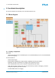
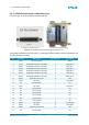
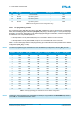
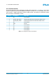
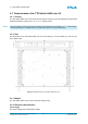
Table Of Contents
- Front Cover
- Table of Contents
- List of Tables
- List of Figures
- Disclaimer
- Limited Rights Notice
- 1 Introduction
- 2 Overview
- 3 Functional description
- 4 Getting started
- 5 State machine
- 6 Creating a switch configuration
- 7 Diagnosis
- 8 Troubleshooting
- Appendix A List of Built-In Self-Tests
- Appendix B Serial terminal output at start-up
- Glossary
- References
- Index

3. FUNCTIONAL DESCRIPTION
Pin Pin Type Description Dip Switch No. Signal Name
22 NC Not connected – NC
23 Ground Dip switch ground – GND
24 Ground Dip switch ground – GND
25 Ground Dip switch ground – GND
Table 2: Pin assignment of the Configuration Plug
3.2.2.1 Pin programming scheme
The programming pins Con_Sel_0 (LSB) to Con_Sel_4 (MSB) are used to represent the configuration
index, whereas Con_Sel_5 is used as the parity bit (even parity). See also Figure 6b on the previous page
and Table 2 on this page. Depending on the selected programming pin combination, a switch configuration
is loaded from one of 16 possible positions.
• If the dip switch is set to position ON, the pin is connected to Ground on the connector.
• If the dip switch is set to position OFF, the pin is not connected at all on the connector.
Table 3 on the current page lists the valid programming pin combinations that are possible for the default
configuration (Con_Sel_0 = OFF).
NOTE
To select a programming pin combination for the actual/backup configuration, set Con_Sel_0 to ON.
Position Con_Sel_0 Con_Sel_1 Con_Sel_2 Con_Sel_3 Con_Sel_4 Con_Sel_5
0 OFF ON ON ON ON ON
1 OFF OFF ON ON ON OFF
2 OFF ON OFF ON ON OFF
3 OFF OFF OFF ON ON ON
4 OFF ON ON OFF ON OFF
5 OFF OFF ON OFF ON ON
6 OFF ON OFF OFF ON ON
7 OFF OFF OFF OFF ON OFF
8 OFF ON ON ON OFF OFF
9 OFF OFF ON ON OFF ON
10 OFF ON OFF ON OFF ON
11 OFF OFF OFF ON OFF OFF
12 OFF ON ON OFF OFF ON
13 OFF OFF ON OFF OFF OFF
14 OFF ON OFF OFF OFF OFF
15 OFF OFF OFF OFF OFF ON
Table 3: Valid programming pin combinations for the default configuration
NOTE
Selecting a new programming pin combination at startup is only possible if the Grnd-Mode dip switch is
set to ON, i.e. if unrestricted mode is active.
© TTTech Computertechnik AG 2020. All rights reserved.
Confidential and Proprietary Information
13
Document Number:
D-A664Lab-G-05-001