
User's Manual
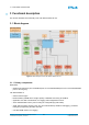
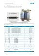
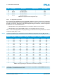
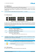
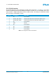
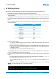
Table Of Contents
- Front Cover
- Table of Contents
- List of Tables
- List of Figures
- Disclaimer
- Limited Rights Notice
- 1 Introduction
- 2 Overview
- 3 Functional description
- 4 Getting started
- 5 State machine
- 6 Creating a switch configuration
- 7 Diagnosis
- 8 Troubleshooting
- Appendix A List of Built-In Self-Tests
- Appendix B Serial terminal output at start-up
- Glossary
- References
- Index

3. FUNCTIONAL DESCRIPTION
3.2.2 CONFIG interface and configuration plug
Connector type: 25-pin D-sub female connector (DB-25S)
(a) The DB-25S CONFIG interface (b) The DB-25P configuration plug
Figure 6: The CONFIG interface of the TTE-Switch A664 Lab v2.0
The DB-25P configuration plug (see Figure 6b on this page) makes it possible to select configurations and
operating modes of the switch.
Pin Pin Type Description Dip Switch No. Signal Name
1 Output Reset push button – RESET
2 Output Configuration selection 0 dip switch 1 CON_SEL_0
3 Output Configuration selection 1 dip switch 2 CON_SEL_1
4 Output Configuration selection 2 dip switch 3 CON_SEL_2
5 Output Configuration selection 3 dip switch 4 CON_SEL_3
6 Output Configuration selection 4 dip switch 5 CON_SEL_4
7 Output Configuration selection 5 dip switch 6 CON_SEL_5
8 Output Reserved for future use 9 RFU
9 Output Dip switch 7 Shop-Mode
10 NC Not connected – NC
11 Output Dip switch 8 Write_Prot
12 NC Not connected – NC
13 NC Not connected – NC
14 NC Not connected – NC
15 NC Not connected – NC
16 NC Not connected – NC
17 NC Not connected – NC
18 Output Dip switch 10 WD_Disable
19 Output Dip switch 11 Grnd-Mode
20 Output Maintenance dip switch 12 RFU
21 NC Not connected – NC
© TTTech Computertechnik AG 2020. All rights reserved.
Confidential and Proprietary Information
12
Document Number:
D-A664Lab-G-05-001