Ultrastore Rapid GE Operating instructions Installation instructions To be kept in the vehicle! Page 3 Page 9
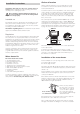
Ultrastore Rapid GE Showering with the Ultrastore Rapid GE The Truma Ultrastore Rapid GE has 10 litre capacity. It is more than capable of heating enough water to give out three consecutive hot showers. When using the boiler, you should observe the following points to achieve this: – Switch the Ultrastore on 16 minutes before required use. – Switch on dual power mode (gas and electricity), Gas operation – 70 °C / electric operation – 1300 W – Set the mixing tap in the shower to approx.
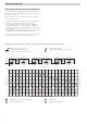
Table of contents Symbols used Symbols used ........................................................................ 3 Safety instructions ............................................................ 4 Important operating notes ............................................... 4 Symbol indicates a possible hazard. Comment including information and tips. Operating instructions Filling the Truma Ultrastore with water ................................. Draining the water heater ...............................
Safety instructions The use of upright gas cylinders from which gas is taken in the gas phase is mandatory for the operation of gas regulators, gas equipment and gas systems. Gas cylinders from which gas is taken in the liquid phase (e.g. for fork lifts) must not be used, since they would result in damage to the gas system. Items sensitive to heat (e.g. spray cans) must not be stored in the installation area, since excess temperatures may under circumstances be incurred there.
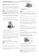
Operating instructions Switching on Gas operation Ultrastore Always observe the operating instructions prior to starting! The vehicle owner is responsible for the correct operation of the appliance. The installer or vehicle owner must apply the yellow sticker with the warning information, which is enclosed with the appliance, to a place in the vehicle where it is clearly visible to all users (e.g. on the wardrobe door)! Ask Truma to send you stickers, if necessary.
The electrical heating element is equipped with an overtemperature sensor. In the event of a fault, switch off at the operating element. Check water content, refill if required (close drain valve). Wait 10 minutes, then switch on again. Maintenance We recommend to use twice a year the Truma system care set for cleaning, disinfecting and looking after the boiler. Other products – in particular products containing chlorine – are unsuitable.
Trouble-shooting list Fault Cause Rectification – No 12 V supply voltage. – Check the power supply (operation voltage min. 10.5 V). Gas operation When switching on, the heater does not operate. – Check the water heater fuse (refer to mainanance “Fuses”). When switching on, the heater does not operate and the red lamp lights up after approx. 30 secs. – Window open. – Close any windows above the cowl. – Cowl cover fitted. – Remove cowl cover and / or clear any obstruction. – No gas supply.
Declaration of conformity Manufacturer’s terms of warranty 1. Information about the manufacturer 1. Case of warranty Name: Truma Gerätetechnik GmbH & Co. KG Address: Wernher-von-Braun-Str. 12, D-85640 Putzbrunn The manufacturer grants a warranty for malfunctions in the appliance which are based on material or production faults. In addition to this, the statutory warranty claims against the seller remain valid. 2.
Installation instructions Installation and repair are only to be carried out by an expert. Always read and follow the operating instructions carefully prior to starting any work! Non-compliance with installation instructions or incorrect installation can result in endangerment of persons and property. Intended use This appliance has been designed for the installation in caravans, motor homes and other vehicles. It is not approved for installation in boats.
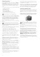
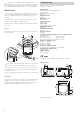
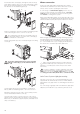
Insert heater with cowl body (1) through the wall cut-out (2), allow approx. 5 mm to project out of the wall. Mount sealing frame (3) (the anti-twisting device ensures correct fitting!). Pre-drill holes for the 6 fastening bolts (4). 1 3 Water connection All pressure and submergible waterpumps up to 2.8 bar and all mixed combination sets with or without an electrical switch, can be used for operating the water heater.
Flexible water hose routing Cut off the ventilation hose approx. 20 mm below the floor of the vehicle at an angle of 45° to the direction of travel. As special accessories Truma supplies the water connectors (12 + 13) and safety/drain (14) valve with a 10 mm diameter hose nipple (please refer to page 14). 21 Pressure-resistant (up to 4.5 bar) and hot water-resistant water hoses in food quality with an internal diameter of 10 mm must be used.
Installation of the control panels Push on the front cover frame (32). When using control panels which are specific to the vehicle or the manufacturer, the electrical connection must be established in accordance with the Truma interface descriptions (refer to Electrical connection 230 V). Any modification made to the Truma components pertaining to this will lead to the invalidation of the guarantee, as well as to the exclusion of any claims for liability.
Electrical connection 230 V Function check The 230 V electrical connection must always be made by an expert (in accordance with VDE 0100, part 721 or IEC 60364-7-721, for example, in Germany). The information given here is not intended as instructions for you to carry out. It is for assisting the expert assigned to carry out the job, acting as auxiliary information when connecting the appliance! After installation, the gas feed line must be tested for tightness by the pressure-drop method.
Accessories Safety/drain valve and water connectors for flexible water hoses 34020-63900 34020-16900 70141-02 Hot water connector, 10 mm Cold water connector, 10 mm Safety/drain valve (4.5 bar), 10 mm Shut-off device To use when the cowl is fitted under a opening part of a window (only to use together with an appropriate window switch).
Notes
In Germany, always notify the Truma Service Centre if problems are encountered; in other countries the relevant service partners should be contacted (see Truma Service Booklet or www.truma.com). 70020-33900 · 04 · 11/2011 · Om · © Having the equipment model and the serial number ready (see type plate) will speed up processing.