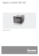
Saphir comfort RC AU Installation instructions
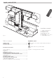
Saphir comfort RC AU 3b 3b 5 Fig. 2 4 3a 3b Installation example 1 2b 1 2a 2b 3a 3b 4 5 2a Fig. 1 Symbols used Table of contents Symbols used ..................................................................... 4 Technical data ..................................................................... 5 Installation dimensions ......................................................... 5 2 The device must only be installed and repaired by an expert. Symbol indicates a possible hazard.
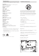
Technical data Installation instructions Determined on the basis of EN 14511 or Truma test conditions –– 1 Saphir comfort RC AU –– 1 Remote control with batteries –– 1 IR receiver –– 4 Fastening brackets with screws, 1 clamping strap –– 2 Condensation traps –– 2 Floor grilles –– 1 Installation template –– 1 set of operating instructions / installation instructions Intended use This device has been designed for installation in motor homes and caravans and is intended for use in the private sector.
The device must always be installed so that it is easy to access at all times for service work, and also easy to remove and install. In the event of restricted installation space being available, the 2 connector cables (power and IR receiver cable) must be of sufficient length for the device to be pulled out with the cables attached and the cover to be opened. 628 mm Installing the air conditioning system Place installation template in stowage compartment and fix in position.
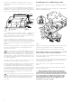
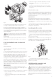
4 p 6 n 4 10 –– Connect the longest cold air duct (max. 8m) to the righthand cold air outlet (9), since this has the highest air throughput. –– In order to avoid condensation, do not route the cold air ducts in the vicinity of inflowing outside air (or behind the refrigerator). Circulated air return 7 8 9 3 2 11 2 3 11 LE LA 1 5 Fig. 6 Lead clamping strap (4) through the 2 fastening brackets (3) – lettering on clamping strap should be facing the floor.
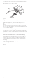
It is imperative that connection is carried out with care while observing the correct cable colours! 18 20 19 17 Fig. 8 Plug connector of IR receiver cable (17) into the socket (19). The connection (18) is a Com connection for communication purposes, and is not needed to operate the device. The cables must be long enough for the device to be pulled out of the false floor with the cables attached.
In Australia, always notify the Service Australia if problems are encountered; in other countries the relevant service partners should be contacted (www.truma.com). Leisure-Tec Australia Pty. Ltd. 50 Metrolink Circuit, Campbellfield, VIC 3061 Australia Service Australia Telephone: +61 1300 07 2018 E-Mail: service@leisure-tec.com.au 40090-00091 · 00 · 01/2019 · © Having the equipment model and the serial number ready (see type plate) will speed up processing.