
User's Manual

CONFIDENTIAL
7 (19)
BTS TPW2458-B-4A/M
Version 1.5
SYSTEM USER GUIDE
Date 22 June 2011
7 Copyright © 2011 TruePath Wireless, LLC. All rights reserved. Reproduction in whole or in part without permission is prohibited. Information contained herein is subject to
change without notice. The specifications and information regarding the products in this document are subject to change without notice. All statements, information, and
recommendations in this document are believed to be accurate, but are presented without warranty of any kind, express, or implied. Users must take full responsibility for their
application of any products. Trademarks, brand names and products mentioned in this document are the property of their respective owners. All such references are used
strictly in an editorial fashion with no intent to convey any affiliation with the name or the product's rightful owner.
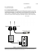
Connector/Feature
Type
Mounting Bracket
Custom bracket that wraps around a pole.
Power Port
RJ-45 connector w/ external weatherproof
enclosure.
Ethernet Port
RJ-45 connector w/ external weatherproof
enclosure.
External Antenna Ports (1-4)
N-type RF connectors
Grounding Nut
Nut/bolt
Alternate Power Connector
n/a
GPS Antenna
SMA female connector used to connect to
external GPS antenna.
Power LED
High-intensity single color (green) LED
Network Activity LED
High-intensity single color (orange) LED
Table 1 - Base Station External Connectors / Features
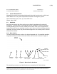
In a multi-sector installation, a GPS is required for transmit and receive synchronization.
Installation of this device is covered in later sections of this document. Likewise, to aid
with lightning protection, the unit is equipped with a grounding nut.
A separate power port is used to allow the addition of high power amplifiers for use in
enterprise-class applications. Additionally, there are two high intensity LEDs that allow
network support personnel the ability to see if the unit is functioning properly from the
ground level.
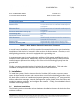
Finally, a custom-mounting bracket is included for pole applications. This and other
installation techniques are covered in later sections of this document.
2. Installation
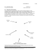
To install the system, first the Internet Service Provider (ISP) needs to procure tower
space for base station sectors and connect them to an Internet backhaul provider. Next,
the back office consists of a webserver/payment gateway hosted by a 3
rd
party provider,
while a radius/User manager, network management system (NMS) client and server are
needed to support, provision, and configure the network. Finally, an embedded client is
installed at the target facility.
2.1 Hardware Installation
The following sections describe various hardware installation features for both the client
and base stations.