
User's Manual

CONFIDENTIAL
12 (19)
BTS TPW2458-B-4A/M
Version 1.5
SYSTEM USER GUIDE
Date 22 June 2011
12 Copyright © 2011 TruePath Wireless, LLC. All rights reserved. Reproduction in whole or in part without permission is prohibited. Information contained herein is subject to
change without notice. The specifications and information regarding the products in this document are subject to change without notice. All statements, information, and
recommendations in this document are believed to be accurate, but are presented without warranty of any kind, express, or implied. Users must take full responsibility for their
application of any products. Trademarks, brand names and products mentioned in this document are the property of their respective owners. All such references are used
strictly in an editorial fashion with no intent to convey any affiliation with the name or the product's rightful owner.
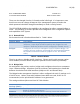
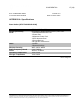
which part of address is the network and that of the host (the mask).
For example, 255.255.255.0 is the most common mask used.
Gateway IP
Represents the address to send non-local data to. The local
network means any network that is configured on the device (i.e.
bridge IP network). In bridge mode, this IP address must be in the
same space as the bridge IP network.
Table 3 - Network Settings (Static)
In bridge network role, the gateway IP address also shows up in the static route table
(covered in a later section).
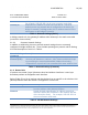
3.1.2.1 Common Network Settings
In addition to addressing, there are several network settings that are commonly
configured in bridge network role. These include spanning tree protocol and IP aliasing.
A list and description of each is in Table 4.
Network Settings
(Common)
Description
Spanning Tree
Protocol (STP)
IEEE 802.1d protocol that works on bridged interfaces to find the
shortest path between to stations. Also, detects and blocks loops
by preventing the same hardware/MAC address from being
accepted from a port that it has transmitted the same address from.
Table 4 - Network Settings (Common)
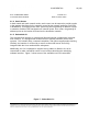
3.1.3 Router Role
IP packets are routed (Layer 3) between wired and wireless interfaces. Lower layer
broadcast packets are dropped at each interface.
Below (Table 5) is a list of settings and descriptions that are specific to the wireless LAN
(WLAN) interface when the device is configured in a router role.
Network Settings
Description
IP Address
IP address used for device management. It is accessible
from the wireless LAN (WLAN) interface.
Netmask
Dotted decimal representation of 4 binary octets that
determine which part of address is the network and that
of the host (the mask). For example, 255.255.255.0 is
the most common mask used.
Table 5 - WLAN Network Settings