
installation guide


39
15 INCH & 24 INCH INSTALL GUIDE
INSTALLING ANTI-TIP BRACKET
ALL FREE STANDING DRAWER (TUR-24-D) OR
STACKED UNITS MUST HAVE THE ANTI-TIP
BRACKETS INSTALLED.
To prevent this the anti-tip brackets need to be
installed. Reconnect the anti-tip bracket if the product
is moved. Failure to follow these instructions can
result in property or bodily harm.
Read all installation instructions first. Install the anti-
tip brackets to hold both rear legs of the unit. Follow
these steps to secure the brackets to the floor before
moving the unit into final operating position.
Contact a qualified floor covering installer for the best
procedure of drilling mounting holes through your type
of floor covering.
BEFORE MOVING UNIT TAKE PRECAUTIONS TO
PROTECT THE FLOOR COVERING.
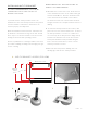
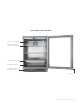
A. Determine the location of the unit. From the front
of the determined location of the lower louver grill
measure back 20 1/2". From the determined side
of the unit measure over 27/32". This is where
the back and outer side of the bracket should sit.
Using the bracket as a template mark the holes for
drilling.
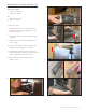
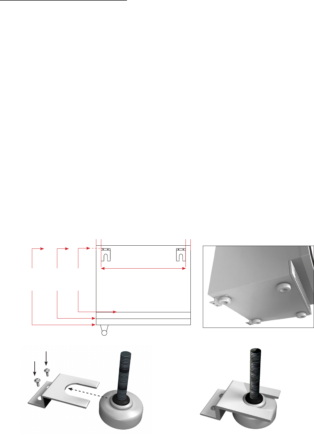
B. To mount the anti-tip bracket to wood floor, drill
pilot holes for each of the bracket holes. To mount
the anti-tip bracket to concrete or ceramic floor
use a masonry bit to drill pilot holes. Align anti-tip
bracket holes with the holes in the floor. Fasten
anti-tip bracket with screws provided using the
brass colored screw for wood, or blue colored
masonry screw for concrete.
C. Move unit into final position making sure rear
leveling legs slide into the anti-tip brackets.
Back of the unit
Cabinet Front
27/ 32" 27/ 32"
22
3/16"
22
25/32"
20
1/2"
Overlay
Panel
22
1/32
"
A - ANTI-TIP BRACKET LOCATOR (TOP VIEW)
B C