
User's Manual


ADA HEIGHT INSTALL GUIDETEC_TM_120 REV. B 02/02/2022 Page 35 of 74
INSTALLATION
ANTI-TIP BRACKET INSTALLATION
KIT CONTENTS
• 2 – Anti-Tip Brackets
• 4 – 3/16" x 2-1/4" Concrete Screws
• 4 – 12 x 2" Phillips Wood Screws
REQUIRED TOOLS
Required tools include (but may not be limited to) the
following:
• Floor Protector
• Tape Measure
• Marking Utensil
• 1/8" Drill Bit*
• Phillips Bit Driver or 1/4" Hex-Head Driver
• Drill
*Drill bit type will vary by flooring material.
CAUTION – ALL FREESTANDING DRAWER
OR STACKED UNITS MUST HAVE ANTI-TIP
BRACKETS INSTALLED.
Install the anti-tip brackets before moving the unit into
its final operating position. Contact a qualified flooring
installer for the best procedure of drilling mounting
holes through your flooring material.
PROCEDURE
1. Place the unit on the floor protector.
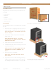
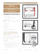
2. Determine the final installation location of the unit.
Measure 27/32" (22 mm) inset from the sides
and either 27/32" from the back or 18-1/2"
(470 mm) from the front (measure does not
include the kickplate). See fig. 1.
IMPORTANT!
ALL FREE STANDING DRAWER OR STACKED
UNITS MUST HAVE ANTI-TIP BRACKETS INSTALLED.
IMPORTANTE!
TOUS LES TIROIRS AUTOPORTANTS OU LES UNITÉS
EMPILÉES DOIVENT AVOIR DES SUPPORTS ANTI-
BASCULEMENT INSTALLÉS.
Anti-Tip Bracket (top view)
Back
Front
18-1/2"
22-3/16"
27/32"
FIG. 1.
Top plan view of anti-tip bracket positioning.
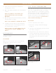
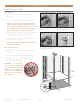
FIG. 2.
Securely fasten the anti-tip brackets to the floor.
FIG. 3.
Be sure the rear leveling legs slide into the brackets.