TRUE RESIDENTIAL® ADA HEIGHT I N S TA L L G U I D E A N D U S E R ' S M A N U A L PRESERVE THE MOMENT® TEC_TM_120 REV.
THANK YOU FOR YOUR PURCHA SE T RUE RE S ID E N TI A L ® 02/02/2022 TEC_TM_102 REV.
I N S TA L L AT I O N C H E C K L I S T To ensure no part of the installation process has been overlooked, complete the checklist below.
CONTENTS INSTALLATION CHECKLIST 3 PRIOR TO INSTALLATION ADA-COMPLIANT INSTALLATION SAFETY INFORMATION & OWNERSHIP ROUGH OPENING & PLAN VIEWS SAFETY WARNINGS & PRECAUTIONS 8 CORRECT DISPOSAL OF OLD REFRIGERATOR 9 16 [32" (813 MM) OPENING] OPTIONAL INSTALLATION ROUGH OPENING & PLAN VIEWS OWNERSHIP 12 [34-1/2" (877 MM) OPENING] 21 PRODUCT REGISTRATION 12 CUSTOM OVERLAY PANEL SPECIFICATIONS 25 CONTACT INFORMATION 12 ELECTRICAL INSTALLATION & SAFETY 31 CABINET LOCATION & SPECIFICATIONS 13
CONTENTS CABINET SETUP SHELF INSTALLATION 40 LOGO INSTALLATION 41 OPTIONAL LOCK INSTALLATION 42 DOOR OVERLAY PANEL INSTALLATION 44 DRAWER OVERLAY INSTALLATION 46 90° DOORSTOP INSTALLATION 48 ADJUSTMENTS, SERVICING & REPLACING COMPONENTS SERVICING & REPLACING COMPONENTS 64 REVERSING DOOR 65 DOOR ADJUSTMENT 66 DRAWER ADJUSTMENT 67 FREQUENTLY ASKED QUESTIONS 68 CONTACT US CABINET OPERATION CONTACT INFORMATION CABINET COMPONENTS / ELECTRONIC CONTROL & LIGHT SWITCH LOCATION 50 ELECTRO
NOTES Page 6 of 74 T RUE RE S ID E N TI A L ® 02/02/2022 TEC_TM_102 REV.
S A F E T Y I N F O R M AT I O N & O W N E R S H I P SAFET Y WARNINGS & PRECAUTIONS CO R R EC T D I S P O S A L O F O L D R E F R I G E R ATO R OWNERSHIP P R O D U C T R EG I S T R AT I O N CO N TA C T U S C A B I N E T LO C AT I O N & S P EC I F I C AT I O N S NOTICE TO CUSTOMER OUTDOOR USE PRESERVE THE MOMENT® TEC_TM_120 REV.
S A F E T Y I N F O R M AT I O N & O W N E R S H I P HOW TO M AINTAIN YOUR TRUE REFRIG ER ATOR TO RECEIVE THE MOS T EFFICIENT AND SUCCE SSFUL OPER ATION You have selected one of the finest commercial refrigeration units made. It is manufactured under strict quality controls with only the best quality materials available. Your TRUE cooler, when properly maintained, will give you many years of trouble-free service.
S A F E T Y I N F O R M AT I O N & O W N E R S H I P • DO NOT store explosive substances such as aerosol cans with a flammable propellant in this appliance. PROPER DISP OSAL OF THE C ABINE T • Keep fingers out of the "pinch point" areas; clearances between the doors and cabinet are necessarily small; be careful closing doors when children are in the area.
I N F O R M AT I O N S D E S É C U R I T É E T P R O P R I É T É COMMENT ENTRE TENIR VOTRE RÉFRIG ÉR ATEUR TRUE P OUR UN FONC TIONNEMENT OP TIM AL E T PERFORM ANT. Vous avez choisi l’un des meilleurs réfrigérateurs commerciaux existants. Il a été fabriqué selon les normes de qualité les plus exigeantes et avec les meilleurs composants disponibles sur le marché. S’il est correctement entretenu, votre réfrigérateur TRUE vous offrira des années de fonctionnement sans souci.
I N F O R M AT I O N S D E S É C U R I T É E T P R O P R I É T É • NE STOCKEZ ni n’utilisez de l’essence ou un autre produit volatile ou liquide inflammable à proximité près de cet appareil ou de tout autre appareil. • NE STOCKEZ PAS de substances explosives tels que bombes aérosol à propulseur inflammable dans cet appareil. • Maintenez les doigts à distance des endroits où vous pourriez vous pincer, les espaces entre les portes et entre les portes et l’armoire sont nécessairement très réduits.
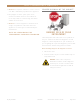
S A F E T Y I N F O R M AT I O N & O W N E R S H I P OWNERSHIP REG IS TER YOUR PRODUC T To ensure that your unit works properly from the first day, it must be installed properly. We highly recommend a trained refrigeration mechanic and electrician install your True equipment. The cost of a professional installation is money well spent. To qualify for TRUE’s extended 7–12 year parts only sealed system warranty, you must register your product* within 12 months of the unit’s installation date.
S A F E T Y I N F O R M AT I O N & O W N E R S H I P C ABINE T LOC ATION & SPECIFIC ATIONS OU TDO OR USE All True undercounter units are rated for outdoor use. For more information regarding the installation location or cabinet specifications, please see “Site Preparation” starting on page 16. • Appliance is NSF 7 approved. • Appliance is UL rated for outdoor use. • In regions with high dewpoints or humidity, condensation may appear on the glass and around gasket seals.
NOTES Page 14 of 74 T RUE RE S ID E N TI A L ® 02/02/2022 TEC_TM_102 REV.
P R I O R TO I N S TA L L AT I O N A D A- CO M P L I A N T I N S TA L L AT I O N ROUGH OPENING & PL AN VIEWS [32" (813 mm) OPENING] O P T I O N A L I N S TA L L AT I O N ROUGH OPENING & PL AN VIEWS [ 3 4 -1 / 2 " ( 8 7 7 m m ) O P E N I N G ] C U S T O M O V E R L AY PA N E L S P EC I F I C AT I O N S E L EC T R I C A L I N S TA L L AT I O N & S A F E T Y PRESERVE THE MOMENT® TEC_TM_120 REV.
P R I O R TO I N S TA L L AT I O N A DA R OUGH OP ENING ADA-COMPLIANT INS TALL ATION ROUG H OPENING & PL AN VIEWS [32 " (81 3 mm) OPENING] The ADA-compliant installation consists of the ADA unit, standard leveling legs, and 4" (102 mm) kickplate. This installation fits beneath an ADA-compliant countertop. For the rough opening and cabinet specifications of alternate installation configurations, please see “Optional Installation Rough Openings & Plan Views” starting on page 21.
A D A- CO M P L I A N T I N S TA L L AT I O N P L A N V I E W S S TAINLE SS SOLID & FR A MED G L A SS DO OR UNIT S R EF R IG ER AT O R S T UR A D A -24 - R / L- R S - A~S W INE C A BINE T T UR A D A -24 - R / L- RG- A~S T U WA D A -24 - R / L- R S - A~S T U WA D A -24 - R / L- RG- A~S BE V ER A G E CEN T ER S TURADA-24-RS-A~S T UB A D A -24 - R / L- RG- A~S 09/24/20 T UB A D A -24 - R / L- R S - A~S P L A N V IE W DIMEN SION S 25 27/32" 657mm 23 7/8" 607mm 23 5/8" 600mm 23 15/16" 608mm 23 5/32" 5
A D A- CO M P L I A N T I N S TA L L AT I O N P L A N V I E W S S TAINLE SS DR AWER UNIT S R EF R IG ER AT O R T UR A D A -24 D - S S - A P L A N V IE W DIMEN SION S TURADA-24-D-A~S 09/24/20 25 27/32" 656mm 23 15/16" 608mm 23 7/8" 607mm 23 5/32" 588mm 44 1/2" 1130mm 31 7/8" 810mm 22 29/32" 582mm 21" 533mm 3 7/8" 98mm 3 3/4" 95mm D im e n si o n s m ay v a r y by ± 1 / 8 " (3. 2 m m) Page 18 of 74 T RUE RE S ID E N TI A L ® 02/02/2022 TEC_TM_102 REV.
A D A- CO M P L I A N T I N S TA L L AT I O N P L A N V I E W S SOLID AND FR A MED G L A SS OVERL AY PANEL UNIT S ADA-Compliant door overlay panel shown. For other panel options, please see “Optional Installation Rough Openings & Plan Views” starting on page 21. For custom panel specifications, please see “Custom Overlay Panel Specifications” starting on page 25.
A D A- CO M P L I A N T I N S TA L L AT I O N P L A N V I E W S OVERL AY PANEL DR AWER UNIT S R EF R IG ER AT O R T UR A D A -24 - D - A~O TURADA-24-D-A~O P L A N V IE W DIMEN SION S* 23 15/16" 608mm 23 7/8" 607mm 23 5/32" 588mm 13 7/8" 352mm 31 7/8" 810mm 42 5/8" 1083mm 9/32" 7mm 21 1/32" 534mm 3 7/8" 98mm 3 3/4" 95mm *D e p t h m e a su r e m e n t in clu d e s 3 /4" t hi ck p a n el (n o t p r o v i d e d by T RUE ). D im e n si o n s m ay v a r y by ± 1 / 8 " (3.
O P T I O N A L I N S TA L L AT I O N R OUGH OP ENING OP TIONAL INS TALL ATION ROUG H OPENING & PL AN VIEWS [3 4-1 /2 " (87 7 MM) OPENING] Optional installations use combinations of 2-1/2" (64 mm) leveling legs, 6" (153 mm) grill, and custom overlay panels to raise (or appear to raise) the overall height of the unit. For standard installation rough openings & plan views, see page 16. This section shows the cabinet specifications for the following configurations: HEIGHT 34-1/2" (877 mm) A.
O P T I O N A L I N S TA L L AT I O N P L A N V I E W S A & B . 2-1 /2 " (6 4 MM) LE VELING LEGS WITH 6" (1 53 MM) G RILL AND S TANDARD D OOR (OVERL AY PANEL) To order a 6” (153 mm) grill (stainless steel or black) or the 2-1/2" (64 mm) leveling legs please contact our parts department at 844-849-6226 or TrueResidentialParts@TrueMfg.com. For custom panel specifications, please see “Custom Overlay Panel Specifications” starting on page 25.
O P T I O N A L I N S TA L L AT I O N P L A N V I E W S C . 2-1 /2 " (6 4 MM) LE VELING LEGS WITH 6" (1 53 MM) G RILL AND TALL D O OR OVERL AY PANEL (D OOR E X TENDS DOWN) To order the stainless steel 6" grill or the 2-1/2" (64 mm) leveling legs please contact our parts department at 844-849-6226 or TrueResidentialParts@TrueMfg.com. For custom panel specifications, please see “Custom Overlay Panel Specifications” starting on page 25.
O P T I O N A L I N S TA L L AT I O N P L A N V I E W S D. S TANDARD LE VELING LEGS WITH TALL DO OR OVERL AY PANEL (DO OR E X TENDS UP) For custom panel specifications, please see “Custom Overlay Panel Specifications” starting on page 25.
O P T I O N A L I N S TA L L AT I O N CUS TOM OVERL AY PANEL SPECIFIC ATIONS Overlay units can be fitted with custom panels to match adjacent cabinetry. Please see this section for recommended panel specifications. NO T E: PA NEL HEIGH T C A N E XCEED T HE SE R EC OMMENDAT ION S B A SED ON R OUGH OP ENING SI Z E A ND C A BINE T SP ECIF IC AT ION S. True units assume 3/4" (19mm) thick overlay panels of the specified width (see spefiications tables) to be supplied by the end user or others.
ADA OVERLAY ADA OVERLAY DOOR DOOR O P T I O N A L I N S TA L L AT I O N S TANDARD SOLID D OOR OVERL AY PANEL – OP TIONAL INS TALL ATIONS A & B For panel installation instructions, please see “Door Overlay Panel Installation” (page 44). For optional lock installation instructions, please see “Optional Lock Installation” (page 42). 23 5/8" 600mm 23 5/8" 600mm 3/4" 19mm SPECIFICATIONS Panel Width 23-5/8" (600 mm) Panel Height 28" (711 mm) Panel Depth 3/4" (19 mm) max Panel Weight 10 lbs (4.
O P T I O N A L I N S TA L L AT I O N DR AWER OVERL AY PANEL For panel installation instructions, please see “Drawer Overlay Panel Installation” (page 46).
O P T I O N A L I N S TA L L AT I O N 6" (1 53 MM) OVERL AY LOU VER G RILL TEMPL ATE – OP TIONAL INS TALL ATIONS A , B , & C 6" GRILL TEMPLATE 23 3/4" 603mm 0" 0mm 11 7/8" 302mm 2-1/2" (64 mm) leveling legs create a visible gap between the bottom of the grill and the floor. To conceal this gap with overlay, please see the custom overlay louver grill template below. 1/2" 13mm 0" 0mm 3/4" 19mm 1 3/4" 44mm 5 15/16" 151mm 3/4" 19mm 3/4" 19mm 1 15/32" 37mm .1250 2X .1250 2X .5000 X 20.
O P T I O N A L I N S TA L L AT I O N ADDITIONAL D OOR OVERL AY PANEL INFORM ATION • Custom door overlay panels must be at least 23-5/8" (600 mm) x 28" (711 mm) x 3/4" (19 mm) to cover the panel-ready door front. Your panel dimensions may vary based on the rough opening size and / or adjacent cabinetry specifications. 23 7/8" 607mm TURADA-24-RS-A~O • For correct hinge operation, be sure to install door overlay panels with its hinge side aligned flush with the door front’s hinge side.
O P T I O N A L I N S TA L L AT I O N ADDITIONAL DR AWER OVERL AY PANEL INFORM ATION • Custom drawer overlay panels must be at least 23-7/8" (607 mm) x 13-5/8" (346 mm) x 3/4" (19 mm) to cover the panel-ready door front. Your panel dimensions may vary based on the rough opening size and / or adjacent cabinetry specifications. • Drawer fronts have pre-drilled holes to assist overlay panel installation. See fig 2.
P R I O R TO I N S TA L L AT I O N ELEC TRIC AL INS TALL ATION & SAFE T Y NEM A P L UG C ONF IGUR AT ION S NEVER USE AN ADAPTER PLUG! An adapter plug alters the original OEM plug configuration when connecting it to a power source. 60 HZ USE ONLY! TRUE uses these types of NEMA plugs shown. If you DO NOT have the proper outlet, have a licensed electrician verify and install the correct power source. TRUE will not warranty any refrigerator/freezer that has been connected to an adapter plug.
P R I O R TO I N S TA L L AT I O N ELEC TRIC AL INS TALL ATION & SAFE T Y (CONT.) HO W T O C ONNEC T EL EC T R ICI T Y • Repair or replace immediately all power cords that have become frayed or otherwise damaged. DO NOT use a power cord that shows cracks or abrasion damage along its length or at either end. • The power cord from this appliance is equipped with a grounding plug which minimizes the possibility of electric shock hazard.
I N S TA L L AT I O N U N C R AT I N G A N T I -T I P B R A C K E T I N S T A L L A T I O N L E V E L I N G L EG I N S TA L L AT I O N LEVELING K I C K P L AT E I N S TA L L AT I O N PRESERVE THE MOMENT® TEC_TM_120 REV.
I N S TA L L AT I O N UNCR ATING R EQUIR ED T O O L S Required tools include (but may not be limited to) the following: • Cutting Tool • Hammer • Crowbar • Phillips Screwdriver • Floor Protector FIG. 1. Pull the cardboard from the pallet. P R O CEDUR E The following procedure is recommended for uncrating the unit: 1. Remove the outer packaging (cardboard and clear plastic). See fig. 1. Inspect for concealed damage. Again, immediately file a claim with the freight carrier if there is damage. 2.
I N S TA L L AT I O N IMP OR TA N T ! Anti-Tip Bracket (top view) ALL FREE STANDING DRAWER OR STACKED UNITS MUST HAVE ANTI-TIP BRACKETS INSTALLED. Back 27/32" IMP OR TA N T E! TOUS LES TIROIRS AUTOPORTANTS OU LES UNITÉS EMPILÉES DOIVENT AVOIR DES SUPPORTS ANTIBASCULEMENT INSTALLÉS. 22-3/16" 18-1/2" ANTI-TIP BR ACKE T INS TALL ATION K I T C ON T EN T S • 2 – Anti-Tip Brackets Front • 4 – 3/16" x 2-1/4" Concrete Screws FIG. 1. Top plan view of anti-tip bracket positioning.
I N S TA L L AT I O N 3. Position the anti-tip brackets and mark the mounting hole locations. 4. With a 1/8" drill bit, drill pilot holes at the marked locations. NO T E: BE SUR E T O U SE A D R IL L BI T A P P R OP R I AT E F O R YOUR F L O O R ING M AT ER I A L . 5. With the appropriate provided hardware, install the anti-tip brackets. See fig. 2. NO T E: T HE C ONCR E T E S CR E W S A R E BL UE . 6. Carefully position the unit in its final installation location.
I N S TA L L AT I O N LE VELING KICKPL ATE INS TALL ATION Proper leveling of your TRUE unit is critical to operating success. Leveling impacts effective condensate removal and door operation. P R O CEDUR E 1. Locate the kickplate secured to the back of the unit. With the cabinet in the final installation location, level the unit front-to-back and side-to-side. 2. Position the kick plate below the door. See fig. 1. P R O CEDUR E 3. Verify the kickplate correctly aligned. Adjust as needed. 1.
NOTES Page 38 of 74 T RUE RE S ID E N TI A L ® 02/02/2022 TEC_TM_102 REV.
CABINET SETUP S H E L F I N S TA L L AT I O N LO G O I N S TA L L AT I O N O P T I O N A L LO C K I N S TA L L AT I O N D O O R O V E R L AY I N S TA L L AT I O N D R AW E R O V E R L AY I N S TA L L AT I O N 9 0 ° D O O R S TO P I N S TA L L AT I O N PRESERVE THE MOMENT® TEC_TM_120 REV.
CABINET SETUP SHELF INS TALL ATION P R O CEDUR E 1. Hook the shelf clips into the shelf standards. See fig. 1. 2. Push up on the bottom of the clip. See fig. 2. NO T E: YOU M AY NEED T O S QUEE Z E O R T W I S T T HE B O T T OM O F T HE SHEL F CL IP F O R P R OP ER IN S TA L L AT ION. P O SI T ION A L L F OUR SHEL F CL IP S EQUA L IN DI S TA NCE F R OM T HE F L O O R F O R F L AT SHELV E S. FIG. 1. Installing top tab of shelf clip. FIG. 2. The bottom tab of the shelf clip will fit tightly FIG. 3.
CABINET SETUP LOGO INS TALL ATION For door units, the TRUE logo ships separately to keep the door field reversible. For instructions on reversing the door, see “Reversing Door” (page 65). When the door is oriented as desired, install the logo as described below. P R O CEDUR E TURADA-24-RS-A~S 1. Locate the logo in the interior packaging. See fig. 1. 2. Determine the desired location for the logo. True typically puts the logo at the midpoint (see fig. 2). 3.
23 5/8" 600mm CABINET SETUP OP TIONAL LO CK INS TALL ATION Follow the instructions below to install a lock assembly in your overlay panel. If converting to overlay from stainless, reuse the existing lock. Otherwise, to order a lock assembly, please contact our parts department at 844-849-6226 or TrueResidentialParts@TrueMfg.com. R EQUIR ED T O O L S ADA OVERLAY DOOR FOR 6" GRILL WITH LOCK 28" 711mm Required tools include (but may not be limited to) the following: FIG. 1.
CABINET SETUP OP TIONAL LOCK INS TALL ATION (CONT.) 3. Install the lock assembly in the door panel. See fig. 4. NO T E: BE SUR E T HE L O CK C A M T UR N S T OWA R D S T HE L O CK BR A CK E T NO T CH. 4. Install the overlay panel. See “Door Overlay Panel Installation” (page 44). See fig. 5. 5. Install the door assembly. See figs. 6 and 7. 6. Verify the door alignment and that the gasket seals without gaps. See fig. 8. Adjust as needed. FIG. 6. Be sure the lock is correctly aligned with the lock bracket.
CABINET SETUP D O OR OVERL AY PANEL INS TALL ATION NO T E: IF C ON V ER T ING F R OM S TA INL E S S S T EEL D O O R SK IN T O A N O V ER L AY PA NEL , R EMO V E T HE D O O R SK IN BEF O R E P O SI T IONING T HE D O O R F R ON T ON T HE PA NEL . D O NO T R EMO V E T HE D O O R SK IN BR A CK E T F R OM T HE D O O R F R ON T. SEE F IG. 2. Follow the instructions below to install door overlay panels.
CABINET SETUP D O OR OVERL AY PANEL INS TALL ATION (CONT.) FIG. 1. The articulating hinge uses keyhole slots. FIG. 2. STAINLESS STEEL MODELS ONLY: Remove the indicated door skin bracket screws. FIG. 3. Pull the gasket from the door. FIG. 4. Be sure the edges are aligned before clamping the door assembly. FIG. 5. Carefully drill pilot holes in the panel. FIG. 6. Carefully fasten the panel to the door front. FIG. 7. Be sure the gasket is fully seated in the gasket channel. FIG. 8.
CABINET SETUP DR AWER OVERL AY PANEL INS TALL ATION Follow the instructions below to install drawer overlay panels. For custom panel specifications, please see “Custom Overlay Panel Specifications” starting on page 25.
CABINET SETUP DR AWER OVERL AY PANEL INS TALL ATION (CONT.) FIG. 3. Pull the gasket from the drawer. FIG. 4a. Drill pilot holes through the drawer front assembly. FIG. 4b. Pilot hole locations. FIG. 5. Be sure the edges are aligned before clamping the drawer front assembly. TOP DRAWER BOTTOM DRAWER FIG. 6. Top drawer bracket skin bracket orientation vs. bottom drawer skin bracket orientation. TEC_TM_120 REV. B FIG. 7. Carefully fasten the panel to the drawer front.
CABINET SETUP DR AWER OVERL AY PANEL INS TALL ATION (CONT.) FIG. 8. Be sure the gasket is fully seated in the gasket channel. FIG. 9. Be sure the drawers close with the gaskets flush against the unit. 90 ° D O ORS TOP INS TALL ATION (OP TIONAL ACCE SSORY ) The doorstop will restrict the door from opening past approximately 90° to prevent damage to surrounding cabinets. NO T E: BE SUR E T O P U T A D O O R S T OP P IN IN B O T H T HE T OP A ND B O T T OM HING E S. SEE F IG S. 1 A ND 2. FIG. 2.
C A B I N E T O P E R AT I O N CABINET COMPONENTS / ELEC TRONIC CONTROL A N D L I G H T S W I T C H LO C AT I O N EL EC T R O N I C CO N T R O L D I S P L AY CO D E S UNLOCK THE CONTROL TURN OFF / ON CONTROL CHANGE THE SET POINT I N I T I AT E M A N U A L D E F R O S T C H A N G E D I S P L AY R E A D O U T PRESERVE THE MOMENT® TEC_TM_120 REV.
C A B I N E T O P E R AT I O N REFRIG ER ATOR / FREE ZER COMP ONENT S Articulating Hinge Serial Label Location Adjustable shelves (2) Removable kick plate for easy cleaning Door Lock Electronic Temperature Control location behind the kickplate Page 50 of 74 T RUE RE S ID E N TI A L ® 02/02/2022 TEC_TM_102 REV.
C A B I N E T O P E R AT I O N WINE C ABINE T COMP ONENT S Articulating Hinge Serial Label Location Floor Wine Cradle Removable kick plate for easy cleaning Door Lock Electronic Temperature Control location behind the kickplate TEC_TM_120 REV.
C A B I N E T O P E R AT I O N REFRIG ER ATED DR AWERS Serial Label Front center ceiling Exclusive True®-Glide Soft-Close feature for both drawers Removable kick plate for easy cleaning Electronic Temperature Control location behind the kickplate Page 52 of 74 T RUE RE S ID E N TI A L ® 02/02/2022 TEC_TM_102 REV.
C A B I N E T O P E R AT I O N ELEC TRONIC CONTROL OPER ATION ELEC TRONIC CONTROL LEGEND Compressor Running ECO Defrost / Back / Show °F or °C °C °F Set Point / Up Arrow Evaporator Fan Running Cabinet in Defrost Power / Okay Set Point / Down Arrow Alarm EL EC T R O N I C D I S P L AY CO D E S Display TEC_TM_120 REV.
C A B I N E T O P E R AT I O N ELEC TRONIC CONTROL OPER ATION ELEC TRONIC CONTROL LEGEND Compressor Running Defrost / Back / Show °F or °C ECO °C °F Set Point / Up Arrow Evaporator Fan Running Cabinet in Defrost Power / Okay Alarm Set Point / Down Arrow UNLO CK THE CONTROL T URN OFF / ON THE CONTROL The display will not lock unless it was originally locked. Turning off the control will deactivate all electrical components. 1. Press any button to display the current lock status. ECO °C °F 2.
C A B I N E T O P E R AT I O N ELEC TRONIC CONTROL OPER ATION ELEC TRONIC CONTROL LEGEND Compressor Running Defrost / Back / Show °F or °C ECO °C °F Set Point / Up Arrow Evaporator Fan Running Cabinet in Defrost Power / Okay Set Point / Down Arrow TURN ON Press and hold the power button until the display shows on. The display will then show the current cabinet temperature. CHANG E THE SE T P OINT Changing the set point adjusts the cabinet temperature to keep optimal product temperature. 1.
C A B I N E T O P E R AT I O N ELEC TRONIC CONTROL OPER ATION ELEC TRONIC CONTROL LEGEND Compressor Running Defrost / Back / Show °F or °C ECO °C °F Set Point / Up Arrow Evaporator Fan Running Cabinet in Defrost Power / Okay Alarm Set Point / Down Arrow INITIATE M ANUAL DEFROS T CHANG E DISPL AY RE AD OU T A manual defrost clears accumulated frost and ice from the evaporator coil. The defrost will only terminate when a specific preset temperature or duration has been met.
MAINTENANCE, CARE & CLEANING CONDENSER COIL CLEANING CO N D E N S AT I O N S TA I N L E S S S T E E L EQ U I P M E N T C A R E & C L E A N I N G PRESERVE THE MOMENT® TEC_TM_120 REV.
MAINTENANCE, CARE & CLEANING C AU T ION – TA K E C A R E DUR ING OP ER AT ION, M A IN T EN A NCE , O R R EPA IR S T O AV OID CU T S O R P INCHING F R OM A N Y C A BINE T PA R T/ C OMP ONEN T. AT T EN T ION – L O R S D E L’ U T IL I S AT ION, D E L’ EN T R E T IEN OU D E S R ÉPA R AT ION S, IL FAU T P R END R E SOIN D ’ É V I T ER L E S C OUP UR E S E T L E S P INCEMEN T S P OU VA N T SUR V ENIR AU C ON TA C T D E S P IÈCE S OU DE S C OMP O S A N T E S D E L’A R MOIR E .
MAINTENANCE, CARE & CLEANING IMP ORTANT WARR ANT Y INFORM ATION T HE CL E A NING O F T HE C OND EN SER I S NO T C O V ER ED BY WA R R A N T Y ! If you have any questions, please contact your local TRUE Manufacturing Service Department. See contact information on pages 12, or 70. • Condenser coils accumulate dirt and require cleaning every 30 days or as needed. FIG. 1. Pull the kickplate off the magnets. • A dirty condenser coil can result in non-warranteed repairs and/or cabinet failure.
MAINTENANCE, CARE & CLEANING S TAINLE SS S TEEL EQUIPMENT C ARE & CLE ANING CAUTION – Do not use any steel wool, abrasive or chlorine based products to clean stainless steel surfaces. S TA INL E S S S T EEL OP P ONEN T S There are three basic things which can break down your stainless steel’s passivity layer and allow corrosion to rear its ugly head. • Scratches from wire brushes, scrapers, and steel pads are just a few examples of items that can be abrasive to stainless steel’s surface.
MAINTENANCE, CARE & CLEANING S TAINLE SS S TEEL EQUIPMENT C ARE & CLE ANING (CONT.) 8 T IP S T O HEL P P R E V EN T RU S T ON S TA INL E S S S T EEL • Maintain the Cleanliness of Your Equipment – Avoid build-up of hard stains by cleaning frequently. Use cleaners at the recommended strength (alkaline chlorinated or non-chloride). • Use the Correct Cleaning Tools – Use non-abrasive tools when cleaning your stainless steel products.
NOTES Page 62 of 74 T RUE RE S ID E N TI A L ® 02/02/2022 TEC_TM_102 REV.
ADJUSTMENTS, SERVICING & REPL ACING COMPONENTS SERVICING & REPL ACING COMPONENTS REVERSING DOOR DOOR ADJUSTMENT DR AWER ADJUSTMENT F R E Q U E N T LY A S K E D Q U E S T I O N S CO N TA C T U S PRESERVE THE MOMENT® TEC_TM_120 REV.
ADJUSTMENTS, SERVICING & REPL ACING COMPONENTS SERVICING & REPL ACING COMP ONENT S NO T E: A N Y C A BINE T A D JU S T MEN T S A R E T O BE M A D E A F T ER T HE C A BINE T H A S BEEN V ER IF IED L E V EL A ND P R OP ER LY SUP P O R T ED. • Replace component parts with original equipment manufacturer (OEM) components. • Contact the dealer or our parts department at 844-849-6179 or TrueResidentialParts@truemfg.com for replacement parts.
ADJUSTMENTS, SERVICING & REPL ACING COMPONENTS RE VERSING D OOR R EQUIR ED T O O L S • 1/8" Hex Head Allen Wrench • Drill (Optional) P R O CEDUR E 1. Loosen the hinge bolts and remove the door See fig. 1. NO T E: D O NO T R EMO V E T HE HING E S F R OM T HE D O O R . FIG. 1. Do not remove the hinge bolts. 2. Move the remaining hardware to the opposite corners. See fig. 2. NO T E: T HE D O O R L O CK P O SI T ION I S DIF F ER EN T F O R E A CH SID E .
ADJUSTMENTS, SERVICING & REPL ACING COMPONENTS D OOR AD J US TMENT Door skin bracket screw holes are slotted to assist with door adjustment. See figs. 1 and 2. P R O CEDUR E 1. Loosen the screws securing the door skin / panel to the door skin bracket. See fig. 1. NO T E: D O NO T R EMO V E T HE S CR E W S. 2. Adjust the door skin / panel as needed. See fig. 2. FIG. 1. Door skin bracket screw location. Not all locations shown. 3. Tighten the door skin bracket screws. 4.
ADJUSTMENTS, SERVICING & REPL ACING COMPONENTS DR AWER AD JUS TMENT Drawer front bracket and skin bracket screw holes are slotted to assist with drawer adjustment. See figs. 1-4. P R O CEDUR E 1. Loosen the drawer front bracket screws. See fig. 1. 2. Adjust the drawer front as needed. See fig. 2. 3. Tighten the drawer front bracket screws. 4. Verify drawer alignment. If more alignment is needed, continue to steps 5 and 6. 5. Loosen the screws securing the drawer skin to the drawer skin bracket. See fig.
ADJUSTMENTS, SERVICING & REPL ACING COMPONENTS FREQUENTLY A SKED QUE S TIONS UNDERCOUNTER How do I adjust the temperature? Please see "Change the Set Point" (page 55). Why does the evaporator fan motor constantly run? This is normal. The evaporator fan motor runs continuously to ensure even temperature throughout your cabinet. The fan only stops when the door is opened to prevent warm air from being circulated throughout the cabinet.
ADJUSTMENTS, SERVICING & REPL ACING COMPONENTS FREQUENTLY A SKED QUE S TIONS (CONT.) Can I put units flush against each other without spacing? In areas with typical climate-controlled temperature/ humidity, yes, True cabinets can be installed side-byside without spacing. However, in humid, non-climate controlled areas, be sure to leave at least a 5/8" (1.58 cm) gap between the cabinets, or install foam pads between the cabinets and on any side with 0" clearance, to prevent moisture from developing.
CO N TA C T U S CONTAC T INFORM ATION For any questions about installation, please contact your TRUE dealer or TRUE Residential Technical Service. Please have your model and serial number (see serial label location below) available so we can better assist you with your service – or parts-related inquiries. CUSTOMER SERVICE TECHNICAL SERVICE DEPARTMENT WARRANTY DEPARTMENT Phone: 888-616-8783 Phone: 844-746-9423 Phone: 844-849-6179 info@true-residential.com TrueResidentialService@truemfg.
NOTES TEC_TM_120 REV.
A DA T R U E R E S I D E N T I A L® WA R R A N T Y S TAT E M E N T TWO-YEAR PARTS & LABOR WARRANT Y TRUE® warrants to the original purchaser of every new TRUE refrigerated unit, the cabinet and all parts thereof, to be free from defects in material or workmanship under normal and proper use and maintenance as specified by TRUE and upon proper installation and start-up in accordance with the instruction packet supplied with each TRUE unit.
D É C L A R AT I O N D E G A R A N T I E P O U R A DA T R U E R E S I D E N T I A L® GARANTIE DE DEUX ANS PIÈCES ETMAIN-D’OEUVRE TRUE garantit à l’acheteur original de chaque nouvelle unité de réfrigération TRUE, l’armoire et toutes les parties de celle-ci, contre toute défectuosité de matériel ou de fabrication, selon des conditions d’ utilisation normale et correcte et un service d’entretien, comme spécifié par TRUE, ainsi qu’une installation correcte et un démarrage en conformité avec le paquet d’instru
CONTACT US true-residential.com | t o ll f r e e 8 8 8 .616. 878 3 BP_178865_01.22 636.240.2400 T RUE RE S ID E N TI A L ® 02/02/2022 TEC_TM_102 REV.