INSTALLATION MANUAL TRUE MANUFACTURING CO., INC. SPEC SERIES®: STR, STA & STG, ROLL-IN AND ROLL-THROUGH CONGRATULATIONS! You have just purchased the finest commercial refrigerator available. You can expect many years of trouble-free operation.
TRUE WWW.TRUEMFG.COM SPEC SERIES®: STR, STA & STG, ROLL-IN AND ROLL-THROUGH NOTICE TO CUSTOMER Loss or spoilage of products in your refrigerator/ freezer is not covered by warranty. In addition to following recommended installation procedures you must run the refrigerator/freezer 24 hours prior to usage. SAFETY INFORMATION How to Maintain Your True Refrigerator to Receive the Most Efficient and Successful Operation. You have selected one of the finest commercial refrigeration units made.
TRUE WWW.TRUEMFG.COM SPEC SERIES®: STR, STA & STG, ROLL-IN AND ROLL-THROUGH DANGER! RISK OF CHILD ENTRAPMENT PROPER DISPOSAL OF THE REFRIGERATOR Child entrapment and suffocation are not problems of the past. Junked or abandoned refrigerators are still dangerous… even if they will sit for “just a few days.” If you are getting rid of your old refrigerator, please follow the instructions below to help prevent accidents. BEFORE YOU THROW AWAY YOUR OLD REFRIGERATOR OR FREEZER: • Take off the doors.
TRUE WWW.TRUEMFG.COM SPEC SERIES®: STR, STA & STG, ROLL-IN AND ROLL-THROUGH INSTALLATION OWNERSHIP LOCK AND KEYS To ensure that your unit works properly from the first day, it must be installed properly. We highly recommend a trained refrigeration mechanic and electrician install your TRUE equipment. The cost of a professional installation is money well spent. The following procedure is for locking and unlock unit: A. Insert the key and turn. B. Remove the key.
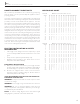
TRUE WWW.TRUEMFG.COM SPEC SERIES®: STR, STA & STG, ROLL-IN AND ROLL-THROUGH HOW TO CONNECT ELECTRICITY WIRE GAUGE CHART Do not, under any circumstances, cut or remove the ground prong from the power cord. For personal safety, this appliance must be properly grounded. 115 Volts Amps The power cord of this appliance is equipped with a grounding plug which mates with a standard grounding wall outlet to minimize the possibility of electric shock hazard from this appliance.
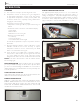
TRUE WWW.TRUEMFG.COM SPEC SERIES®: STR, STA & STG, ROLL-IN AND ROLL-THROUGH LOCATING SEALING CABINET TO FLOOR 1. Make sure unit is as close to the final location as possible. 2. Remove the shipping bolts located at the bottom of the wooden skid. 3. Carefully slide the unit off the wooden skid. Slide packing material underneath the side of the unit hanging off the skid. Then install castors or legs for that side of the unit.
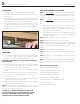
TRUE WWW.TRUEMFG.COM SPEC SERIES®: STR, STA & STG, ROLL-IN AND ROLL-THROUGH ROLL-IN & ROLL-THRU RAMP INSTALLATION DOOR SWEEP GASKET ADJUSTMENT Once the cabinet is in its final location and level the roll-in ramp can be installed. The ramp has three slotted holes in back. These slotted holes slide over three thumb screws located in the front of the cabinet near the floor. To adjust door sweeper gasket, loosen slotted thumbscrews. The gasket can then be moved up or down and side to side.
TRUE WWW.TRUEMFG.COM SPEC SERIES®: STR, STA & STG, ROLL-IN AND ROLL-THROUGH SETUP STANDARD ACCESSORIES DOOR CONFIGURATION: After installing, cabinet doors can be adjusted for alignment. The hinge on the door and hinge on the cabinet can be adjusted accordingly. STEP 1 To remove door open at a 90˚ angle from the cabinet and lift door up and out from the cabinet hinges carefully avoiding rainshield. Rest the door in a safe area. STEP 2 Remove gray plastic cover from hinge located on the cabinet.
TRUE WWW.TRUEMFG.COM SPEC SERIES®: STR, STA & STG, ROLL-IN AND ROLL-THROUGH OPERATION STARTUP DIGITAL TEMPERATURE DISPLAY A. The compressor is ready to operate. Plug in the cooler. The digital temperature display can view ˚C or ˚F. To achieve this, there is a small plug that will need to be removed to achieve ˚C reading. See image 1 for temperature display location. If the plug is kept in the back of the digital display ˚F will be viewable. See images for reference.
TRUE SPEC SERIES®: STR, STA & STG, ROLL-IN AND ROLL-THROUGH WWW.TRUEMFG.COM MECHANICAL TEMPERATURE CONTROLS COIL SENSING An evaporator coil sensing temperature control ensures that the evaporator coil will remain clear of frost and ice by not allowing the compressor to restart until the coil temperature is above the freezing temperature. This is considered an off cycle defrost.
TRUE SPEC SERIES®: STR, STA & STG, ROLL-IN AND ROLL-THROUGH WWW.TRUEMFG.COM MECHANICAL CONTROL FREEZER GENERAL SEQUENCE OF OPERATION 1. Cabinet is plugged in. a. Interior lights will illuminate on glass door models only. If lights do not come on, verify the light switch is in the “ON” position. Solid door cabinets may or may not have lights that may be controlled by the door switch. 2. The compressor only will start if the temperature control is calling for cooling.
TRUE WWW.TRUEMFG.COM SPEC SERIES®: STR, STA & STG, ROLL-IN AND ROLL-THROUGH WHEN TO MAKE AN ADJUSTMENT TO A MECHANICAL TEMPERATURE CONTROL We advise to make a mechanical temperature control adjustment only for a high altitude location.
TRUE WWW.TRUEMFG.COM SPEC SERIES®: STR, STA & STG, ROLL-IN AND ROLL-THROUGH INSTRUCTIONS: DANFOSS TEMPERATURE CONTROL ADJUSTMENT FOR HIGH ALTITUDE APPLICATIONS STEP 1 - Unplug cooler. STEP 2 - Remove the screws that secure the temperature control to the inset box. STEP 3 - To make these adjustments it may be necessary to remove the temperature control from the housing. NOTE: You may have to remove the wires attached to the control. Take note as to which wire is on which spade terminal.
TRUE WWW.TRUEMFG.COM SPEC SERIES®: STR, STA & STG, ROLL-IN AND ROLL-THROUGH CHART 2 8 7 6 42° 78° 114° 150° 186° 222° 258° 294° 330° 3 4 1 9 2000' 3000' 4000' 5000' 6000' 7000' 8000' 9000' 10,000' 5 O Height CCW Adjustment (based on 360°/ complete turn) O 1 CUT OUT BUL. NO.
TRUE SPEC SERIES®: STR, STA & STG, ROLL-IN AND ROLL-THROUGH DEFROST TIMER WWW.TRUEMFG.COM DEFROST TIME CLOCK OPERATION FOR UNITS WITH MECHANICAL CONTROL NOTICE: If timer is not set for a minimum of 3 defrost per day for 30 minutes each, the coil may develop excessive frost. This may lead to system failure and product loss, which is not covered under warranty. RECOMMENDED DEFROST SETTINGS: The following procedure may be followed to customize your needs.
TRUE WWW.TRUEMFG.COM SPEC SERIES®: STR, STA & STG, ROLL-IN AND ROLL-THROUGH ELECTRONIC TEMPERATURE CONTROLS LAE ELECTRONIC TEMPERATURE CONTROL GENERAL SEQUENCE OF OPERATION t1 = Thermostat t2 = Defrost t3 = Display t3 probe is not installed and / or activated in all applications when t3 is not installed and / or activated, the display probe is t1. LAE ELECTRONIC CONTROL GENERAL SEQUENCE OF OPERATION 1. Cabinet is plugged in. a. Display will illuminate. b.
TRUE WWW.TRUEMFG.COM SPEC SERIES®: STR, STA & STG, ROLL-IN AND ROLL-THROUGH HOW TO DIAGNOSE AN LAE ELECTRONIC CONTROL Indicator lights for Refrigeration/Heating Mode, Fan Operation, Defrost Mode.
TRUE WWW.TRUEMFG.COM SPEC SERIES®: STR, STA & STG, ROLL-IN AND ROLL-THROUGH LAE Control Info / Set Point Button Manual Defrost / Down Button Manual Activation Up Button Stand-By Button HOW TO TURN OFF THE LAE ELECTRONIC CONTROL: May need to unlock control. WHY: Turning off the control will deactivate all electrical components. CAUTION: Turning off the control will not shut off power to the cabinet. Cabinet must be unplugged prior to any repair.
TRUE WWW.TRUEMFG.COM SPEC SERIES®: STR, STA & STG, ROLL-IN AND ROLL-THROUGH LAE Control Info / Set Point Button Manual Defrost / Down Button Manual Activation Up Button Stand-By Button CHANGING THE "SET POINT": May need to unlock control. WHY: The set point is the temperature at which the compressor will shut off. NOTE: The “set point” IS NOT the cabinet holding temperature. 1 HOW TO CHANGE THE “SET POINT”: STEP 1 - To see the set point, press and hold the Info button See image 1.
TRUE WWW.TRUEMFG.COM SPEC SERIES®: STR, STA & STG, ROLL-IN AND ROLL-THROUGH LAE Control Info / Set Point Button Manual Defrost / Down Button Manual Activation Up Button Stand-By Button INITIATE A MANUAL DEFROST: May need to unlock control. WHY: A one time additional defrost may be necessary to clear accumulated frost / ice from evaporator coil. HOW TO INITIATE A MANUAL DEFROST: The method to initiate a manual defrost is determined by the Defrost Mode Parameter “DTM” preprogrammed in the controller.
TRUE WWW.TRUEMFG.COM SPEC SERIES®: STR, STA & STG, ROLL-IN AND ROLL-THROUGH LAE Control CHANGING “DEFROST INTERVALS”: May need to unlock control. Info / Set Point Button Manual Defrost / Down Button Manual Activation Up Button Stand-By Button 1a This can only be changed if defrost mode parameter “DFM” is set for “TIM”. WHY: The defrost interval is the time duration between defrost cycles. The defrost interval time starts when the cabinet is supplied power or after a manual defrost.
TRUE WWW.TRUEMFG.COM SPEC SERIES®: STR, STA & STG, ROLL-IN AND ROLL-THROUGH LAE Control HOW TO CHANGE DISPLAY READOUT FROM FAHRENHEIT TO CELSIUS: Info / Set Point Button Manual Defrost / Down Button Manual Activation Up Button Stand-By Button 1a May need to unlock control. This can NOT be changed with the LAE model AR2-28 version of the control. See page 32 for more information. WHY: Changing readout will assist with customer application.
TRUE WWW.TRUEMFG.COM SPEC SERIES®: STR, STA & STG, ROLL-IN AND ROLL-THROUGH LAE Control Info / Set Point Button Manual Defrost / Down Button Manual Activation Up Button Stand-By Button DISPLAYING TEMPERATURE PROBES, T1, T2, T3: WHY: To display temperature probe readings in different locations of the cabinet. 1 HOW TO DISPLAY PROBE TEMPERATURES: STEP 1 - To display T1 temperature, press and release the info button . “t1” will appear. See image 1.
TRUE WWW.TRUEMFG.COM SPEC SERIES®: STR, STA & STG, ROLL-IN AND ROLL-THROUGH LAE CONTROLLER PARAMETER SETTINGS FOR CELSIUS (X-32) / 1.8 (X-32) / 1.8 SU BJ EC (20-32) / 1.8 = -6.7 Celsius (X) / 1.8 23 (X) / 1.8 (X) / 1.8 (X-32) / 1.8 (X-32) / 1.8 (X) / 1.8 (X) / 1.8 ADO AHM AHT ACC IISM IISL IISH IISP IIHY IIFC HDS IIDF SB DS DSM DI2 STT EDT LSM OA1 OA2 CD INP OS1 T2 OS2 T3 OS3 TLD TDS AVG SIM ADR (X-32) / 1.8 (X-32) / 1.8 (X-32) / 1.8 (X-32) / 1.8 (X) / 1.
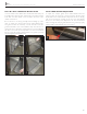
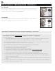
TRUE WWW.TRUEMFG.COM SPEC SERIES®: STR, STA & STG, ROLL-IN AND ROLL-THROUGH MAINTENANCE, CARE, CLEANING CLEANING THE CONDENSER COIL When using electrical appliances, basic safety precautions should be followed, including the following. Disconnect power to unit. TOOLS REQUIRED • Phillips Screwdriver • Air Tank or CO2 Tank • Stiff Bristle Brush • Vacuum Cleaner • Adjustable Wrench STEP 1: Disconnect power to unit. STEP 2: Remove all screws securing top screen to unit. See image 1.
TRUE WWW.TRUEMFG.COM SPEC SERIES®: STR, STA & STG, ROLL-IN AND ROLL-THROUGH IMPORTANT WARRANTY INFORMATION Condensers accumulate dirt and require cleaning every 30 days. Dirty condensers result in compressor failure, product loss, and lost sales... which are not covered by warranty. If you keep the Condenser clean you will minimize your service expense and lower your electrical costs. The Condenser requires scheduled cleaning every thirty days or as needed.
TRUE WWW.TRUEMFG.COM SPEC SERIES®: STR, STA & STG, ROLL-IN AND ROLL-THROUGH STAINLESS STEEL EQUIPMENT CARE AND CLEANING 8 STEPS THAT CAN HELP PREVENT RUST ON STAINLESS STEEL: CAUTION: Do not use any steel wool, abrasive or chlorine based products to clean stainless steel surfaces. 1. USING THE CORRECT CLEANING TOOLS Use non-abrasive tools when cleaning your stainless steel products. The stainless steel’s passive layer will not be harmed by soft cloths and plastic scouring pads.
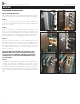
TRUE SPEC SERIES®: STR, STA & STG, ROLL-IN AND ROLL-THROUGH WWW.TRUEMFG.COM GENERAL MAINTENANCE LIGHT BULB REPLACEMENT (INTERIOR LIGHTS) GENERAL MAINTENANCE WARNING: When replacing a light bulb make sure power to the unit is either turned off or unplugged. Be careful when removing the light bulb. Please be aware of your local ordinances in disposing old bulbs. These bulbs should be disposed in a safe and correct manner. • Simply unscrew the light bulb. See images 1 & 2.
TRUE WWW.TRUEMFG.COM SPEC SERIES®: STR, STA & STG, ROLL-IN AND ROLL-THROUGH WARRANTY INFORMATION (U.S.A. & CANADA ONLY!) THIS WARRANTY ONLY APPLIES TO UNITS SHIPPED FROM TRUE'S MANUFACTURING FACILITIES AFTER SEPTEMBER 1, 2015.