
Installation Guide and User's Manual
ManualsBrandsTrue Residential ManualsAll Refrigerator- No Freezer36 Inch Refrigerator Column with 19.7 Cu. Ft. Capacity, Stainless Steel Interior, Adjustable Glass Shelves, Stainless Steel Crisper Drawers with Integrated Handles, Intuitive True Precision® Digital Controls, Ramp-up LED lighting and 24.7 cu. ft. Capacity


TRUE RESIDENTIAL
®
TEC_TM_009 Rev.A
June 6, 2019 Page 6 of 44
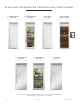
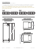
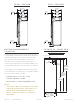
ELECTRICAL REQUIREMENTS
TR-30/TR-36
For all built-in models, the electrical supply should be
located within the shaded area shown in the illustration.
Follow the National Electrical Code and local codes
and ordinances when installing the receptacle. A
dedicated circuit, supplying only this appliance is
required. A ground fault circuit interrupter (GFCI) is not
recommended and may cause interruption of operation.
If the supply cord is damaged, it must be replaced by
the manufacturer, its service agent or similarly qualified
person in order to avoid a hazard.
• POWER SUPPLY 115 V AC, 60 HZ
• CIRCUIT BREAKER 15 AMP
• RECEPTACLE 3-PRONG GROUNDING-TYPE
NOTES:
• THE OUTLET MUST BE CHECKED BY A QUALI-
FIED ELECTRICIAN TO BE SURE THAT IT IS
WIRED WITH THE CORRECT POLARITY.
• VERIFY THAT THE OUTLET IS PROPERLY
GROUNDED.
TR-30/TR-36 – FRONT VIEW
ROUGH OPENING &
ELECTRICAL AREA
84"
(2134 mm)
PROUD
INSTALL
84
1
/
4
"
(2140 mm)
FLUSH
INSTALL
77"
(1956 mm)
2"
(51 mm)
8"
(204 mm)
Electrical located
in this area.
30
1
/
4
"
(769 mm)
29
3
/
4
"
(756 mm)
FLUSH
INSTALL
PROUD
INSTALL
30"
762mm
67 29/32"
1725mm
DOOR
HEIGHT
72 5/8"
1845mm
83 15/16"
2132mm
25 25/32"
655mm
27 29/32"
709mm
30 15/32"
774mm
2 9/16"
65mm
3 15/16"
100mm
135°
20 19/32"
523mm
23 25/32"
604mm
55 1/4"
1403mm
29 15/32"
748mm
31 15/32"
799mm
90°
29 9/16"
751mm
TR-30REF-R-SS-A
R
36"
915mm
83 15/16"
2132mm
72 5/8"
1845mm
67 29/32"
1725mm
DOOR
HEIGHT
3 15/16"
100mm
27 29/32"
709mm
25 25/32"
655mm
30 15/32"
774mm
2 9/16"
65mm
90°
23 25/32"
604mm
35 9/16"
903mm
61 1/4"
1556mm
37 15/32"
952mm
35 15/32"
901mm
135°
24 13/16"
631mm
TR-36REF-R-SS-A
R
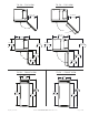
TR-30 – SIDE VIEW TR-36 – SIDE VIEW