
Technical Specifications

UP
UP
UP
INSTRUCTIONS FOR INSTALLATION OF
SINGLE AND DOUBLE CYLINDER DEADLOCKS
FOR USE ON DOORS 1-3/8" TO 1-3/4" (35mm-45mm)
5.INSTALL EXTERIOR MECHANISM
TORQUE BLADE
SHOULD BE
HORIZONTALLY
INSERTED INTO
LATCH CRANK
A. Press cylinder side flush against door making certain
the torque blade is properly positioned in latch crank.
B. Tapped holes in mounting plate of exterior cylinder
should be lined up with latch holes. Key hole should
be in down position.
6.INSTALL INTERIOR MECHANISM
A. Slide thumb bar and interior rosette onto
torque blade.
B. Insert machine screws through holes
engaging holes in cylinder and tighten.
1" THROW
TURN
PIECE
Exterior half is fully assembled with exterior torque blade
EXTERIOR TORQUE BLADE
NOTE: The interior torque blade is inserted into the exterior blade.
INTERIOR TORQUE BLADE
A. Install interior cylinder
NOTE: This assembly is placed through latch first.
B. Press interior assembly flush against door
making certain the torque blade is
properly positioned
in latch hole. Key
hole should be in
down position.
C. Insert(2) two screws through countersunk
holes engaging holes in exterior cylinder
and tighten.
1.MARK DOOR
A. Fold and apply template to high edge of
door bevel and mark center of door edge
as indicated on
template at
the desired
height from
the floor.
B. Mark center hole on door face through
guide on template
for either 2-3/8"
(60mm) or
2-3/4"
(70mm)
backset.
2.DRILL HOLES
A. Drill thru door face as marked for lockset:
It is recommended that holes be drilled from
both sides to prevent spliting. Hole size is 2"
(50.8mm) for
standard
installations.
B. Drill 1"(25mm)
hole in center
of door edge
thru to
2"(50.8mm)
hole for
latch.
B. Chisel 1/8"
deep or until
latch face is
flush with
door edge.
C. Install deadbolt latch in
up position into
hole as shown
on latch insert
and tighten
screws.
D. For round face deadbolt press flush to
door edge
Bolt must
be vertically
aligned with
door edge
as indicated
by arrow.
4.INSTALL STRIKE
A. Bore 1" hole 1"minimum deep
for deadbolt.
B. Mortise 1/16" deep for strike
locating from 1" hole in door
insert and tighten screws.
UP
A. Insert latch in hole keeping it parallel to
face of door. Mark
outline and
remove latch.
UP
UP
TORQUE
BLADE
2-3/8" BACKSET
2-3/4" BACKSET
2-3/8" BACKSET
2-3/4" BACKSET
3.INSTALL LATCH
INSTRUCTIONS FOR INSTALLING
DOUBLE CYLINDER DEADLOCKS
FOR INSTALLING
DEADLOCKS
NOTE:
TEMPLATE MUST
BE PLACED ON
HIGH EDGE OF
DOOR BEVEL
MARK
PROPER
DOOR
THICKNESS
DRILL 1"(25mm)
HOLE IN EDGE OF DOOR
(2" IN DEPTH)
READ INSTRUCTIONS
1 "(45mm)THICK
DOOR
1 " 35mm
THICK
DOOR
2 "(70mm)
2 "(60mm)
FOLD HERE
2 /
8
"BACKSET
3
3
4
3
4
3
8
3
8
DRILL
2"(50.8mm)
HOLE
BACKSET
DISTANCE
MARK
UP
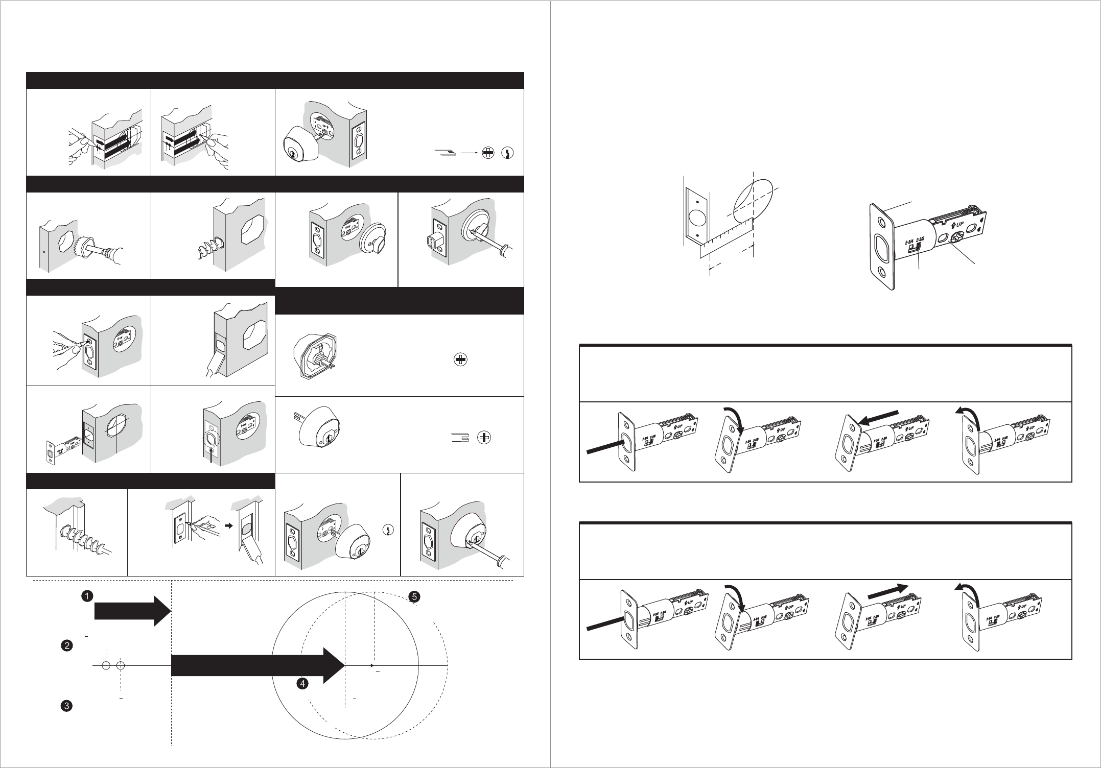
To adjust the backset from 2-3/8" to 2-3/4" follow these steps.
Retract the latch bolt.
Hold the latch tail and
rotate the faceplate
towards you.
Rotate the latch faceplate
away from you and check
to see if the notch is at
the 2-3/4" mark.
(A)
2-3/8" - or - 2-3/4"
(60 mm) (70 mm)
UP
Latch Faceplate
Latch Tail
Selecting the Proper Backset
The backset is the distance from the door edge to the center of the hole
To adjust the backset from 2-3/4" to 2-3/8" follow these steps.
Once the notch is in
the groove, pull the
latch faceplate away
from the latch tail.
Retract the latch bolt.
Hold the latch tail and
rotate the faceplate
towards you.
Rotate the latch faceplate
away from you and check
to see if the notch is at
the 2-3/8" mark.
Once the notch is in
the groove, push the
latch faceplate towards
the latch tail.
UP
UP
Notch
UP
UP
UP
UP
UP