Operator's Manual 2 -Cycle Gasoline Model TB75SS or IMPORTANT: READ SAFETY RULES AND INSTRUCTIONS P/N 769-00734 (4/03) PRINTED IN USA CAREFULLY
THANKYOU TABLE OF CONTENTS Thank you for buying this quality product. This modern outdoor power tool will provide many hours of useful service. You will find it to be a great labor-saving device. This operator's manual provides you with easy-tounderstand operating instructions. Read the whole manual and follow all the instructions to keep your new outdoor power tool in top operating condition. Service Information ......................... Rules for Safe Operation Know Your Unit .......................
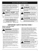
The purpose of safety symbols is to attract your attention to possible dangers. The safety symbols, and their explanations, deserve your careful attention and understanding. The safety warnings do not by themselves eliminate any danger. The instructions or warnings they give are not substitutes for proper accident prevention measures. SYMBOL SYMBOL MEANING DAI Ir_I:'D. Failure toobeya rl =v,_,= i.. ='l. Safety warning will result in serious injury to yourself or to others.
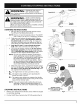
• Alwaysstoptheengineandallowit tocoolbeforefilling thefueltank.Neverremove thecapofthefueltank,or addfuel,whentheengineishot.Neveroperatetheunit withoutthefuelcapsecurelyinplace.Loosenthefuel tankcapslowlytorelieveanypressure inthetank. • Mixandaddfuelinaclean,well-ventilated outdoorarea wheretherearenosparksorflames.Slowlyremovethe fuelcaponlyafterstoppingengine.Donotsmokewhile fuelingor mixingfuel.Wipeupanyspilledfuelfromthe unitimmediately. Alwayswipeunitdrybeforeusing. • Movetheunitatleast30feet(9.
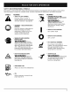
SAFETY AND INTERNATIONAL SYMBOLS This operator's manual describes safety and international symbols and pictographs that may appear on this product. Read the operator's manual for complete safety, assembly, operating and maintenance and repair information. SYMBOL MEANING SYMBOL Indicates danger, warning, or caution. May be used in conjunction • SAFETY ALERT SYMBOL with other symbols or pictographs.
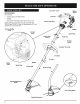
EZ-Start APPLICATIONS As a trimmer: TM Muffler Guard Lever Fuel Cap Cutting grass and light weeds. Edging Decorative trimming around trees, fences, etc. Starter Rope Grip_ Other optional accessories may be used with the TB75SS and TB25CS. Refer to Operating the EZ-Link System for a list of add-ons. Air Filter/Muffler Cover \ \ \ Muffler EZ-Start Lever \ Spark Plug Shaft Grip Control _ Throttle Control Shoulder Strap Clip D-Handle EZ.Link \ Engine Stand TM Muffler \\ \ Spark Plug \ Pr
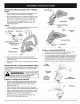
INSTALLING Install AND ADJUSTING THE D-HANDLE 1. Remove the screws and bottom clamp piece that were installed on the D-handle for shipping. 2. Place D-handle the over the shaft housing and onto the bottom clamp (Fig. 1). Place it a minimum of 6 inches (15.24 cm) from the end of the shaft grip. Shaft Housing _ 3. Start screws with a large Flat-head or T-25 Torx screwdriver. Do not tighten until you make the handle adjustment. Shield Mount Cutting Adjust 4.
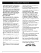
OIL AND FUEL MIXING INSTRUCTIONS Old and/or improperly mixed fuel are the main reasons for the unit not running properly. Be sure to use fresh, clean unleaded fuel. Follow the instructions carefully for the proper fuel/oil mixture. Definition of Blended Fuels Today's fuels are often a blend of gasoline and oxygenates such as ethanol, methanol, or MTBE (ether). Alcohol-blended fuel absorbs water. As little as 1% water in the fuel can make fuel and oil separate. It forms acids when stored.
AlMA D[ILll _11"_.. Operate this unit only in a v u n-L i x i i ni ! t._ • well: ventilated outdoor [ AIIk[__ area.confinedCarbOnarea.mOnox de exhaust fumes can be etha n WARNING: Avoid accidental starting. Make sure you are in the starting position when pulling the starter rope (Fig. 8). To avoid serious injury, the operator and unit must be in a stable position while starting. Make sure that any Add-On item is installed correctly and secure before starting the unit. STARTING INSTRUCTIONS 1.
OPERATING THE EZ-LINW M SYSTEM 2. The EZ-Link TM system enables the use of these optional Add-Ons. Blower/Vacuum ........................... TBBV Cultivator ................................ While firmly holding the add-on, push it straight into the EZ-Link TM coupler (Fig. 10). NOTE: Aligning the release button with the guide recess will help installation (Fig. 9). TBGC Edger ................................... TBLE Hedge Trimmer ........................... Snow Thrower ...........................
HOLDING THE TRIMMER NOTE: Do not rest the Bump Head rM on the ground while the unit is running. uurir_lv!mv_.JI, hearing, foot and body protection to reduce the iisk of injury when operat ng th sun t. Some line breakage will occur from: I Entanglement with foreign matter J Normal line fatigue Before operating the unit, stand in the operating position (Fig. 12).
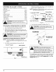
MAINTENANCE SCHEDULE NOTE: Maintenance, replacement, or repair of the emission control devices and system may be performed by any non-road engine repair establishment, individual or authorized service dealer. Perform these required maintenance procedures at the frequency stated in the table. These procedures should also be a part of any seasonal tune-up. NOTE: Some maintenance procedures may require special tools or skills.
. 4. Pull old line out of the line loading and line locking holes (Fig. 16 and 17). Insert a piece of trimming line straight into one of the two eyelets in the outer spool. Push it up through the line loading hole in the inner reel (Fig. 16). Do not bend the line when inserting it into the eyelet. 7. Repeat procedures 4-6 with the second piece of line. 8. Hold the outer spool. Wind the inner reel counterclockwise until approximately four (4) inches (102 mm) of line remain (Fig. 19).
2. Pull the old inner reel with existing line from the outer spool. 3. Insert the ends of the prewound inner reel line into the outer spool eyelets (Fig. 22). Push the new inner reel, arrow side up, into the outer spool. Remove any existing line from the inner reel before cleaning. Remove any debris or grass from the knob, spring, inner reel and foam seal. Wash the inner reel with warm soapy water (Fig. 24). 4, Inner Reel Fig. 24 , 4. Fig.
AIR FILTER MAINTENANCE Removing 1. the Air Filter/Muffler Cover WARNING: To avoid serious personal injuryl always turn your trimmer off and allow it to 1 cool before you clean or service it, J Remove the four (4) screws securing the air filter/muffler cover (Fig. 26). Use a flat blade or T20 Torx bit screwdriver. Air Filter i 2. Pull the cover from the engine, Do not force. Inside Muffler Cover EZ-StartTM Lever Fig. 27 Fig, 28 Screwsl Screws ii iiiiiiiiiiiiiiiiiiiiiiiiiiiiii Fig.
SPARK ARRESTOR 1. 2. MAINTENANCE Remove the air filter/muffler Air Filter/Muffler Cover. cover. See Removing the Spark Arre_or Locate the muffler front and the two (2) bolts securing it to the engine (Fig. 31). Remove the two (2) bolts using a flatblade screwdriver or 5/16-inch socket or nut driver. Pull the muffler off of the engine. \ \ \ \ \ Exhaust Gasket \ 3. Turn the muffler over to the back side and locate the exhaust gasket. Remove the muffler gasket from the muffler (Fig. 31).
CARBURETOR \ ADJUSTMENT The idle speed of the engine is adjustable through the air filter/muffler cover (Fig. 33). NOTE: Careless adjustments can seriously damage your unit. An authorized service dealer should make carburetor adjustments. Check ! Fuel Mixture Old and/or improperly mixed fuel is usually the reason for improper unit performance, Drain and refill the tank with flesh properly-mixed fuel pnor to making any adjustments. Refer to Oil and Fuel Information.
REPLACING THE SPARK PLUG LONG TERM If the unit will be stored for an extended time, use the following storage procedure: 1. Drain all fuel from the fuel tank into a container with the same 2-cycle fuel mixture. Do not use fuel that has been stored for more than 60 days. Dispose of the old fuel/oil mix in accordance to Federal, State and Local regulations. Use a Champion RDJ7Y spark plug (or equivalent). The correct air gap is 0.020 inch (0.5 ram).
CAUSE Emptyfueltank Primerbulbwasn'tpressedenough Engineis flooded Oldor improperly mixedfuel Fouledsparkplug Pluggedsparkarrestor EZ-Startleverwasn'tflipped/set Theoutsidetemperature is below40° F Theoutsidetemperature is above90° F e ACTION Fill fuel tank with properly mixed fuel Press primer bulb fully and slowly 10 times Squeeze the trigger and pull the starter rope Drain gas tank and add fresh fuel mixture Replace or clean the spark plug Clean or replace spark arrestor Move lever to the starting posit
EngineType.......................................................................................................................................... Air-Cooled, 2-Cycle Stroke.................................................................................................................................................... 1.25in.(31.75mm) Displacement ............................................................................................................................................. 1.9cu in.
EPA Emission Control Warranty Statement Your Warranty Rights and Obligations The Environmental Protection Agency and Troy-Bilt LLC (Troy-Bilt) are pleased to explain the emission control system warranty on your 2002 and later small off-road engine. New small off-road engines must be designed, built and equipped to meet stringent anti-smog standards.
ENGINE PARTS - MODEL TB75SS 2-CYCLE GAS TRIMMER - ENGINE Item 1 2 79%180350B Description Air Cleaner/Muffler (includes 2 & 37) Air Cleaner Filter 3 4 5 791-180351 753-1193 753-1194 Carburetor Mounting Choke Extension Choke Plate 6 7 8 753_04338 791_610675 79%181860 Carburetor Assembly Carburetor Gasket Carb Mount Screw 9 10 11 12 791-683974B 753_ 1196 791-684461 753-1208 Primer and Hose Assembly Carb Mount Assembly (includes 8, 11 & 12) Reed Assembly Carburetor Mount Gasket 13 753_04401 14 16
_ BOOM AND TRIMMER PARTS MODEL TB75SS 2 CYCLE TRIMMER - BOOM ® Item 1 2 3 4 5 6 7 8 9 Part No.
ENGINE PARTS - MODEL TB25CS 2-CYCLE GAS TRIMMER - ENGINE Item Part NO.
BOOM AND TRIMMER PARTS MODEL TB25CS 2 CYCLE TRIMMER - BOOM ® ® Item 1 Part NO.
MANUFACTURER'S LIMITED WARRANTY FOR: 0 TROI BI[T" The limited warranty set forth below is given by Troy-Bilt LLC with respect to new merchandise purchasedand used in the United States, its possessions and territories. Troy-Bilt LLC warrants this product against defects in material and workmanship for a period of two (2) years commencing on the date of original purchase and will, at its option, repair or replace, free of charge, any part found to be defective in material or workmanship.