
Manual

OPERATING THE EZ-LINK TM SYSTEM
The EZ-Link TM system enables the use of these optional
Add-Ons:
Blower/Vacuum ........................... TBBV
Cultivator ................................ TBGC
Edger ................................... TBLE
Hedge Trimmer ........................... TBHS
Snow Thrower ............................ TBST
Straight Shaft Trimmer ...................... TBSS
Tree Pruner .............................. TBTP
Turbo Blower ............................. TBTB
_[WARNING: Read and Understand the I
operator s manual [0[ eac h add:on pdo r to
operation.
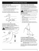
Removing the Cutting Attachment or Add-Ons
1. Turn the knob counterclockwise to loosen (Fig. 6).
2. Press and hold the release button (Fig. 6).
3. While firmly holding the upper shaft housing, pull
the cutting attachment or add-on straight out of the
EZ-Link TM coupler (Fig. 6).
_[WARNING: To avoid serious persona! injury I
and damage to the unit, shut off the unit
before remov ng or nsta I ng add-ons.
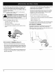
Installing the Cutting Attachment or Add-Ons
NOTE: Place the unit on the ground or on a work bench
to make add-on installation or removal easier.
1. Turn knob counterclockwise to loosen (Fig. 6).
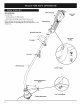
EZ-LinkTMcoupler Release Button
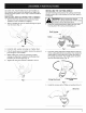
2. While firmly holding the add-on, push it straight into
the EZ-Link rM coupler (Fig. 7).
NOTE: Aligning the release button with the guide recess
will help installation (Fig. 6).
Release Button
EZ-LinkTM Coupler /
Upper Shaft Housing Lower Shaft Housing
Fig. 7
,
Turn the knob clockwise to tighten (Fig. 8).
CAUTION: Lock the release button in the
primary hole and securely tighten the knob
before operat ng ths Unt
90° Edging Hole
(Trimmer Only)
_j
1.o•EdgingHo,e
(Trimmer Only)
Knob
L
Fig. 8
\
Guide Recess
Fig. 6
CAUTION: The cutting attachment and add-
ons with the EZ-LinkTM system are to be used i_
[he primary hole unless stated otherwise in the
specific add-ons operator's manual, Using the
wrong hole could lead to personal injury or
damage to the unit.
For edging (when using the line head cutting attachment
with EZ-Link TM models_ ock the release button of the
cutting attachment into the 90 ° edging hole or the 180°
edging hole (Fig. 8).
8