
Manual


UsingYourStringTrimmerMower
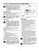
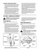
Once the engine is started, release the control lock
bracket on the upper right hand side of the handle
by pushing it to the right and squeeze the control
handle against upper handle to engage spindle
assembly.
The string trimmer mower is designed with a per-
manent off-set on the left side, in which the trimmer
line is off-set from the trimmer base. This allows the
operator to trim along a fence, landscaping, or a
house without having to make any adjustments to
the spindle assembly. Refer to Figure 4.
If the weeds or grass are tall and thick, operate the
string trimmer mower at a slower walking speed.
With the engine off and spark plug disconnected,
clean the underside of the trimmer before and after
each use to remove any grass or weed build up.
If the trimmer lines become too short, approxi-
mately half the original length, or worn, it will take
longer to complete the job. To change to a new
trimmer line see MAINTAINING YOUR STRING
TRIMMER MOWER.
Do not trim on excessively steep slopes. If a slope
is difficult to stand on, do not trim. Do not trim on
slopes when the ground is slippery or wet. Trim
across the face of a slope, not up and down.
Avoid spindle assembly contact to concrete,
asphalt, or gravel.
SECTION6: MAKINGADJUSTMENTS
WARNING: Do not at any time make any
adjustments without first stopping engine
and disconnecting spark plug wire.
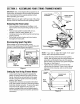
HandleAdjustment
To adjust position of the upper handle proceed as
follows:
Loosen each wing nut, so the carriage bolts are
unseated from the handle and the handle
connectors are slightly separated from each other.
The lower handle connector has three marked lines
on the top and the upper handle connector has one
marked line. See.
To raise the upper handle, move the upper handle
forward to match the single marked line with the
front marked line on the lower handle connector.
To lower the upper handle, move the upper handle
rearward to match the single marked line with the
rear marked line on the lower handle connector.
Marked
Lines
Wing Nut
Lower
Connector
Connectors
Figure 6
Secure the handle connectors in position by
tightening each wing nut (carriage bolts must be
10
seated properly intothe handle and grooves must
line up between connectors). Also make certain the
bottom tip of the upper handle connector in front of
the bottom tip of lower handle connector.
See Figure 6.
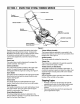
SpindleHeightAdJustment
To adjust height of the spindle assembly proceed as
follows:
The trimmer line is connected to the spindle disc,
which can be raised or lowered. See Figure 7.
The spindle disc in the normal position rest on the
spindle cap approximately 2" offthe ground.
Loosen, but do not remove each wing nut on
spindle shaft.
_k WARNING: The wings nuts are designed
not to be removed from the spindle shaft
by hand or using a tool.
Slide spindle disc along shaft to the desired
position and tighten wing nuts to secure in position.
The spindle disc can be adjusted from 2" to 4".
Trimmer
3ase
Nut
Sp
Disc
Sl: )indle
Cap Shaft
Trimmer
Line
Figure 7