
Manual
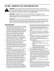

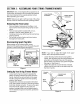
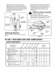

Securethehandleconnectorsinpositionby
tighteningeachwingnut(carriageboltsmustbe
seatedproperlyintothehandleandgroovesmust
lineupbetweenconnectors).Alsomakecertainthe
bottomtipoftheupperhandleconnectorinfrontof
thebottomtipoflowerhandleconnector.
SeeFigure5.
Marked
Lines
Wing Nut
Lower
Connector
er Handle
Connectors
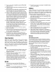
The trimmer line is connected to the spindle disc,
which can be raised or lowered. See Figure 6.
The spindle disc in the normal position rest on the
spindle cap approximately 2" offthe ground.
Loosen, but do not remove each wing nut on
spindle shaft.
WARNING: The wings nuts are designed
not to be removed from the spindle shaft
by hand or using a tool.
Slide spindle disc along shaft to the desired
position and tighten wing nuts to secure in position.
The spindle disc can be adjusted from 2" to 4".
Trimmer
Base
Nut
Sp
Figure 5 Disc
SpindleHeightAdjustment
To adjust height of the spindle assembly proceed as
follows:
SI: )indic
Cap Shaft
Figure 6
Line
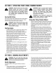
SECTION7: MAINTAININGYOURSTRINGTRIMMERMOWER
CustomerResponsibilities
MAINTENANCE eo-¢. ._o _,v _ y _,9.
SC EOO,E ,o,O/ / ooO,-o,,o,o
Lubricate Wheels
Clean Trimmer Deflector _
_) Check Trimmer Line ,_
Check Belt Tension
Check Oil
Change Oil _ q_
w Replace Air Filter <_
Z
Clean Engine Intake Screen _ £_
w
Check Spark Plug ,_ <_
Check Spark Arrester (if any) _
SERVICE
DATES
10