0 T RoKRILT Operator's Manual Pedal Drive Garden Tractor Models Z809H & Z809K IMPORTANT: Read safety rules and instructions carefully before operating equipment. Warning: This unit is equipped with an internal combustion engine and should not be used on or near any unimproved forest-covered, brush-covered or grass-covered land unless the engine's exhaust system is equipped with a spark arrester meeting applicable local or state laws (if any).
TABLEOFCONTENTS Content Page Important Safe Operation Practices ................................................................... 3 Slope Gauge ...................................................................................................... 6 Tractor Set-up .................................................................................................... 7 Know Your Garden Tractor ................................................................................
SECTION 1: IMPORTANT SAFEOPERATION PRACTICES WARNING: This symbol points out important safety instructions which, if not followed, could endanger the personal safety and/or property of yourself and others. Read and follow all instructions in this manual before attempting to operate this machine. Failure to comply with these instructions may result in personal injury. When you see this symbol--heed its warning.
through unusually tall,drygrass(e.g.,pasture) orpilesof dryleaves. Drygrass orleaves maycontact theengine exhaust and/orbuilduponthemower deckpresenting a potential firehazard. 27. Useonlyaccessories andattachments approved forthis machine bythemachine manufacturer. Read, understand andfollowallinstructions provided withthe approved accessory orattachment. 28. Dataindicates thatoperators, age60yearsandabove, areinvolved ina largepercentage ofridingmowerrelated injuries.
extremely flammable andthevapors areexplosive. Serious personal injurycanoccurwhengasoline is spilled onyourself oryourclothes whichcanignite. Wash yourskinandchange clothes immediately. a. Useonlyanapproved gasoline container. b. Never fillcontainers insideavehicle oronatruck ortrailerbedwithaplastic liner.Always place containers ontheground awayfromyourvehicle before filling. c. Whenpractical, remove gas-powered equipment fromthetruckortrailerandrefuel itontheground.
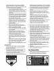
SIGHT AND HOLD THIS LEVEL WITH A VERTICAL TREE .11 A POWER POLE A CORNER OF A BUILDING OR A FENCE POST t.O W 15° I,IJ ..I WARNING &i Z i 1.1.1 Do not mow on inclines with a slope in excess of 15 degrees (a rise of approximately 2-1/2 feet every 10 feet). A riding mower could overturn and cause serious injury. If operating a walk-behind mower on such a slope, it is extremely difficult to maintain your footing and you could slip, resulting in serious injury.
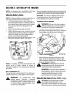
SECTION3: SETTINGUPTHETRACTOR NOTE: Any reference here to the RIGHT or LEFT side of the tractor is observed from operator's position. AttachingBatteryCables NOTE: The positive battery terminal is marked Pos. (+). The negative battery terminal is marked Neg. (-). • • • • The positive cable (heavy red wire) is secured to the positive battery terminal (+) with a hex bolt and hex nut at the factory. Make certain that the rubber boot covers the terminal to help protect it from corrosion.
Adjustthedeckrollerheightsothattheclevispins areinsertedinthesecondhole(fromthetop)of boththeleft-handdeckrollerbracketandtherighthanddeckrollerbracket.SeeFigure5 or referto DeckRollerHeightAdjustment on page 9 for more detailed instructions on adjusting the deck roller upward or downward. • • • Raise the deck lift arms up and out of the way by placing the deck lift lever in the top notch on the right fender. Gently slide the cutting deck beneath the tractor from the right side.
Left-hand Idler Bracket 3/8" Square Hole Spring Figure 4 Deck RollerHeightAdjustment To adjust the height of the rollers found on the rear of the mowing deck upward or downward, proceed as follows: • • • Place the deck lift lever in the bottom notch (lowest position). Remove the clevis pins and hairpin clips from the deck roller brackets on the left and right sides of the cutting deck. See Figure 5.
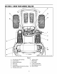
SECTION4: KNOWYOURGARDEN TRACTOR \ G H B J K C L D M Wheel not Figure 6 A B PTO (Power Take-off) Knob Choke Control H I Ignition Switch Brake Pedal C D Parking Brake Button Shift Lever J Drive Pedal K Cruise Control Button E Cup Holder F G Systems Indicator Monitor/Hour Meter Throttle Control Lever L M Seat Adjustment Lever DeckLift Lever 10
Throttle ControlLever Drive Pedal The throttle control lever is located on the right side of the tractor's dash panel. This lever controls the speed of the engine. When set in a given position, the throttle will maintain a uniform The drive pedal is located below the brake pedal on the right front side of the tractor along the running board. Depress the drive pedal with your right foot when the tractor shift lever is in either FORWARD or REVERSE to cause the tractor to move. Fast_=- engine speed.
Deck Lift Lever Indication Found on your tractor's right fender, the deck lift lever is used to change the height of the cutting deck. To use, move the lever to the left, then place in the notch best suited for your application. Brake light on Engage the parking brake. PTO light on Move PTO knob to the disengaged(OFF) position. Parking Brake Button To set the parking brake, fully depress the brake pedal and push the parking brake button in.
SECTION5: OPERATING YOURGARDEN TRACTOR NOTE: The deck wheels are an anti-scalp feature of the deck and are not designed to support the weight of the cutting deck. WARNING AVOIDSERIOUS INJURYORDEATH • • • • • • • • • • • • Refer to LevelingtheDeckon page 16 of this manual for more detailed instructions regarding various deck adjustments. GO UP AND DOWN SLOPES, NOT ACROSS. AVOID SUDDEN TURNS.
DrivingOnSlopes ,_ • Refer to the SLOPEGAUGE on page 6 to help determine slopes where you may operate the tractor safely. WARNING: Do not leavethe thePTO seatknob of thein the tractor without first placing disengaged (OFF) position, depressing the brake pedal and engaging the parking brake. If leaving the tractor unattended, also turn the ignition key off and remove the key. ,_ Depress the brake pedal to release the parking brake and let the pedal up.
UsingtheDeckLiftLever Mowing To raise the cutting deck, move the deck lift lever to the left, then place it in the notch best suited for your application. Refer to SettingTheCuttingHeightearlier in this section. _l children and pets at least 75 feet from the machine while it is in operation. Stop machine if anyone enters the area. Engagingthe PTO The following information will be helpful when using the cutting deck with your tractor.
SECTION6: MAKINGADJUSTMENTS Hex Nut and WARNING: Never attempt to make any adjustments while the engine is running, except where specified in the manual. Pivot Bar WARNING: Disconnect the spark plug wire(s) and ground against the engine before performing any adjustments, repairs or maintenance. Lock_ ParkingBrake WARNING: Never attempt to adjust the brakes while the engine is running.
• Withthetractorparkedonafirm,levelsurface, placethedeckliftleverinthetopnotch(highest position)androtatethebladenearest thedischarge chutesothatitis parallelwiththetractor. Measurethedistancefromfrontofthebladetipto thegroundandrearofthebladetiptotheground. Thefirstmeasurement takenshouldbebetween 1/4"and3/8"lessthanthesecondmeasurement. Determine theapproximate distancenecessary for properadjustment andproceedtothenextstep. Loosenthetwojamnutsontherearsideofthe deckstabilizerbracket.SeeFigure10A.
SECTION7: MAINTAINING YOURGARDEN TRACTOR WARNING: Before performing any maintenance or repairs, disengage PTO, move shift lever into neutral position, set parking brake, stop engine and remove key to prevent unintended starting. Air Cleaner • Service the pre-cieaner, ifso equipped, and cartridge/air cleaner element as instructed in the engine manual. Spark Plugs Engine • Refer to the engine manual for engine maintenance instructions.
IMPORTANT: Makecertainthetractor'sdischarge chute is directedawayfromyourhouse,parkedcars,etc. • Disengage PTO,moveshiftleverintotheneutral position,settheparkingbrake,andstopengine. • Threadthehosecoupler(packaged withthis manual)ontotheendofyourgardenhose. • Attachthehosecouplertothewaterportonyour deckssurface.SeeFigure13. • Turnthewateron. • Whilesittingintheoperator'spositiononthe tractor,re-starttheengineandplacethethrottle leverintheFAST(rabbit)position. • Engagethetractor'sPTO.
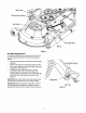
Model 809H Electric PTO Clutch PTO Idler Bracket (mounted on tractor) Deck Idler Pulley _PTO belt (Top) Right Hand Double Pulley (beneath belt guard) \ Left Hand Double Pulley Center Pulley Self-Tapping Screws NOTE: Left hand belt cover not shown for clarity. 46-inch deck shown. Figure 15 To change or replace the deck belts on your tractor, proceed as follows: • • • • • Lower the deck by moving the deck lift lever into the bottom notch on the right fender.
Upper DriveBelt ChangingtheTransmission DriveBelt • WARNING: Be sure to shut the engine off, remove ignition key, disconnect the spark plug wire(s) and ground against the engine to prevent unintended starting before removing the belt(s). • • All belts on your tractor are subject to wear and should be replaced if any signs of damage are observed. NOTE: It is recommended replaced at the same time.
IMPORTANT: Note the routing of the lower drive belt around both the pulleys and the belt keepers before performing the following steps. • • • • • Double-idler Hole side of the pulley. Slide the belt off the variable-speed pulley as you lift the pulley up and out through the battery tray opening. Remove rear idler pulley from the double- idler bracket while loosening the belt from around both the rear and the front idler pulleys. See Figure 17.
The blades may be removed as follows: • • Blade Separation Remove the deck from beneath the tractor, (refer to CuttingBeck Removal on page 19) then gently flip the deck over to expose its underside. Place a block of wood between the center deck housing baffle and the cutting blade to act as a stabilizer. See Figure 20.
Charging If the tractor has not been put into use for an extended period of time, charge the battery with an automotivetype 12-volt charger for a minimum one hour at 6 amps. _ WARNING: Batteries givebattery off an explosive gas while charging. Charge in a well ventilated area and keep away from an open flame or pilot light as on a water heater, space heater, furnace, clothes dryer or other gas appliances.
SECTION 11: TROUBLESHOOTING Trouble Possible Engine fails to start PTO knob engaged. Parking brake not engaged. Spark plug wire(s) disconnected. Throttle control lever not in correct starting position. Choke not activated Fuel tank empty, or stale fuel. Blocked fuel line. Faulty spark plug. Engine flooded. Unit running with CHOKE applied. Spark plug wire(s) loose. Blocked fuel line or stale fuel. Engine runs erratic Corrective Cause(s) Vent in gas cap plugged. Water or dirt in fuel system.
SECTION 12: PARTSLISTFORMODELSZ809H & Z809K (for choke) 18 20_ 16 15 26 14 f
ModelsZ809H& Z809K REF. NO. 1 2 3 4 5 6 7 8 9 10 11 12 13 14 15 16 17 18 19 20 21 22 23 24 PART NO. 710-0227 710-0599 710-0726 710-1237 710-1314A 710-1315 712-3017 721-0460 726-0205 736-0119 736-0300 751B221535 751-0535 751-0564 751-0616 751-0650 751-0651 751-3140 751-3141 751-3142 783-0615B 783-0625C 722-0263 746-1086 DESCRIPTION Self4apping Screw, #8-18 x .6 Self-tapping Screw, 1/4-20 x .6 AB Screw, 5/16-12 x .75 Screw, #10-32 x .625 Socket Cap Screw, 5/16-18 x .626 Self4apping Screw, 3/8-16 x 1.
ModelsZ809H& Z809K 17 21 I 8 22 28
ModelsZ809H& Z809K REP. NO. 1 2 3 4 5 6 7 8 9 10 11 12 13 14 15 16 17 18 19 20 21 22 23 24 25 26 27 28 29 30 31 32 33 34 36 36 37 38 39 40 41 42 43 44 45 46 47 48 49 50 51 52 PART NO.
ModelsZ809H & Z809K 46 38 27 5O 5 3O
ModelsZ809H & Z809K RER NO. 1 2 3 4 5 6 7 8 9 10 11 12 13 14 15 16 17 18 19 20 21 22 23 24 25 26 27 28 29 30 PART NO. 747-1130B 747-1324 683-0197B 683-0462 711-0332 712-0206 712-0431 712-3004A 712-3083 714-0104 714-0145 716-0106 720-0311 732-0874 732-1184 736-0275 736-0921 736-3019 736-3084 738-0138A 738-0143 741-0225 741-0715 746-0968 747-1111A 756-1154 783-0678A 783-0720A 710-0260A 710-0726 710-0895 731-1990 REF. NO.
ModelsZ809H& Z809K j 23 21 14 20 8 30 25 32
ModelsZ809H& Z809K REP. NO. 1 2 3 4 5 6 7 8 9 10 11 12 13 14 15 16 17 18 19 20 21 22 23 24 25 26 27 28 29 30 31 32 33 34 35 36 37 38 39 40 41 PART NO.
ModelsZ809H & Z809K 13 74 I I I 1 I 30 i I I I I I I I I I 114 I I 2 34
ModelsZ809H& Z809K RER NO. 1 2 3 4 5 6 7 8 9 10 11 12 13 14 15 16 17 18 19 20 21 22 23 24 25 26 27 28 29 30 31 32 33 34 35 36 37 38 39 40 41 42 43 44 PART NO.
ModelsZ809H & Z809K ® r" 18 9 12 23 40 5 26 12 32 36
ModelsZ809H& Z809K RED NO. 1 2 3 4 5 6 7 8 9 10 11 12 13 14 15 16 17 18 19 20 21 22 23 24 26 26 27 28 29 30 31 32 33 34 35 36 37 38 39 40 41 42 43 44 46 47 48 49 PART NO.
ModelsZ809H & Z809K (For reference only) I 39 * Found on Model Z809H only 38
ModelsZ809H & Z809K RER NO. 1 2 3a 3b 4a 4b 5 6 7 8 9 10 11 12 13 14 15 16 17 18 19 20 21 22 23 PART NO. 783-0653E 754-0476 717-1709 717-1774 783-1003 783-1487 710-0859 710-1238 712-0431 732-0978 712-3004A 710-3180 712-3010 683-0294 738-3056 710-3144 710-3025 738-0785 736-0171 710-3157 725-1706 710-0751 712-0271 712-3087 725-1426 DESCRIPTION Steering Support Bracket PTO Belt Elec. PTO Clutch (Mod. Z809H) Elec. PTO Clutch (Mod. Z809K) (incl. # 39) PTO Clutch Anti-rot. Brakt.
ModelZ809H 11 4\ 2 5 23 22 17 12 .
ModelZ809H IMPORTANT: For a proper working machine, use Factory Approved Parts. V-belts are designed to engage and disengage safely. A substitute (non OEM) V-belt can be dangerous by not disengaging completely. REF. PART NO. NO. 1. 17982 2. 618-0430A 756-1187 3. 618-0595 756-0603 4. 683-0254 5. 683-04053 6. 710-0167 7. 710-0344 8. 710-0501 9. 710-0514 10. 710-0528 11. 710-0599 12. 710-0650 13. 710-0703 14. 710-0751 15. 710-1260A 16. 711-04069 17. 712-0271 18. 712-0417A 19. 712-0431 20. 712-0641 21.
ModelZ809K 72 44 47 40 39 7 / / / 27 / 50 26 42
ModelZ809K RER NO. 1. 2. 3. 4. 5. 6. 7. 8. 9. 10. 11. 12. 13. 14. 15. 16. 17. 18. 19. 20. 21. 22. 23. 24. 25. 26. 27. 28. 29. 30. 31. 32. 33. 34. 35. 36. 37. 38. 39. PART NO.
MANUFACTURER'S LIMITED WARRANTY FOR: 0 TPD RILT" The limited warranty set forth below is given by Troy-Bilt LLC with respect to new merchandise purchased and used in the United States, its possessions and territories. Troy-Bilt LLC warrants this product against defects for a period of two (2) years commencing on the date of original purchase and will, at its option, repair or replace, free of charge, any part found to be defective in materials or workmanship.