O TRO BILT__ Operator's Manual Pedal Drive Garden Tractor Models V809H Y809P IMPORTANT: READ SAFETY RULES AND INSTRUCTIONS CAREFULLY Warning: This unit is equipped with an internal combustion engine and should not be used on or near any unimproved forest-covered, brush-covered or grass-covered land unless the engine's exhaust system is equipped with a spark arrester meeting applicable local or state laws (if any).
TABLEOFCONTENTS Content Page Important Safe Operation Practices ................................................................... 3 Slope Gauge ...................................................................................................... 7 Tractor Set-up .................................................................................................... 8 Know Your Garden Tractor ................................................................................
SECTION1: IMPORTANT SAFEOPERATION PRACTICES WARNING: This symbol points out important safety instructions which, if not followed, could endanger the personal safety and/or property of yourself and others. Read and follow all instructions in this manual before attempting to operate this machine. Failure to comply with these instructions may result in personal injury. When you see this symbol--heed its warning.
23. Mufflerandenginebecomehotandcancausea burn.Donottouch. 24. Checkoverhead clearances carefullybeforedriving underlowhangingtreebranches, wires,door openingsetc.,wheretheoperatormaybestruckor pulledfromtheunit,whichcouldresultinserious injury. 25. Disengage allattachment clutches,depressthe brakepedalcompletely andshiftintoneutralbefore attempting tostartengine. 26. Yourmachineisdesignedtocutnormalresidential grassofa heightnomorethan10".Donotattempt tomowthroughunusually tall,drygrass(e.g.
e. Useextremecarewhenapproaching blind corners,doorways, shrubs,treesorother objectsthatmayblockyourvisionofa child whomayrunintothemachine. f. Disengage thecuttingblade(s)before shiftinginreverse.The"No-Cut-In Reverse" featureisa remindernottocutinreverseand to helpavoidbackoveraccidents. Donot defeatit. g. Keepchildrenawayfromhotor running engines.Theycansufferbumsfroma hot muffler. h. Removekeywhenmachineis unattended to preventunauthorized operation. 9.
8. Nevertamperwiththesafetyinterlocksystemor othersafetydevices.Checktheirproperoperation regularly. 9. Afterstrikingaforeignobject,stoptheengine, disconnect thesparkplugwire(s)andground againsttheengine.Thoroughly inspectthe machineforanydamage.Repairthedamage beforestartingandoperating. 10. Neverattempttomakeadjustments or repairsto themachine whiletheengineis running. 11.Grasscatchercomponents andthedischarge coveraresubjecttowearanddamagewhichcould exposemovingpartsorallowobjectstobethrown.
SIGHT AND HOLD THIS LEVEL WITH A VERTICAL TREE ,11 A POWER POLE A CORNER OF A BUILDING I nq OR A FENCE POST I iii 15° iii ..I &i Z n iii _WARNING Do not mow on inclines with a slope in excess of 15 degrees (a rise of approximately 2-1/2 feet every 10 feet). A riding mower could overturn and cause serious injury. If operating a walk-behind mower on such a slope, it is extremely difficult to maintain your footing and you could slip, resulting in sedous injury.
SECTION3: TRACTOR SET-UP AttachingtheBatteryCables NOTE: The positive battery terminal is marked Pos. (+). The negative battery terminal is marked Neg. (-). The positive cable (heavy red wire) is secured to the positive battery terminal (+) with a hex bolt and hex nut at the factory. Make certain that the rubber boot covers the terminal to help protect it from corrosion. Remove the hex bolt and wing nut from the negative cable.
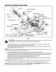
AttachingTheCuttingDeck(ModelY809P) Notches Deck Lift Assembly Lift Cables Deck Lift Arms Deck Support Pins. Deck Stabilizer Bracket j Deck Skid Rod Discharge Chute \ Front of Tractor Deck Stabilizer Rod NOTE: Deck components not shown for clarity. PTO Idler Pulley Bracket (mounted on tractor) Figure 3 ,_ OFF position and remove the keythe from the switch avoid accidental starting.
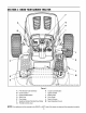
SECTION4: KNOWYOURGARDEN TRACTOR F \ G H B K C L M D NOTE: Steering Figure 4 A B PTO (Power Take-off) Knob Choke Control C D Parking Brake Button Shift Lever H Cruise ControIButton I J Ignition Switch Brake Pedal K Drive Pedal Deck Lift Lever Seat Adjustment Lever E Cup Holder L F G Systems Indicator Monitor/Hour Meter Throttle Control Lever M NOTE: Any reference in this manual to the RIGHT or LEFT side of the tractor is observed from operator's position.
ThrottleControlLever IgnitionSwitch The throttle control lever is located on the right side of the tractor's dash panel. This lever controls the speed of the engine. When set in a given position, the throttle will maintain a uniform engine speed. See Figure 5. WARNING: Never leave a running machine unattended. Always disengage PTO, move shift lever into neutral position, set parking brake, stop engine and remove key to prevent unintended starting.
SystemsIndicatorMonitor/ HourMeter Electric PTO Your tractor is equipped with four indicator lights and an hour meter located on the left side of the dash panel. See Figure 7. (PowerTake-off)Knob Battery To engage the power to the cutting deck or other (separately available) attachments, pull outward on the PTO knob. Push the PTO knob inward to \ disengage the power to the cutting deck.
DeckLift Lever CruiseControlButton The cruise control button is Found on your tractor's right fender, the deck lift lever is used to change the height of the cutting deck. To use, move the lever to the left, then place in the notch best suited for your application. to the left of the ignition switch. located on the tractor dash panel Push the cruise control button while traveling forward at a desired speed. While holding the button in, release pressure from the drive pedal.
DrivingTheTractor from the discharge of the WARNING: Keep opening hands and feet cutting away deck. ,_ WARNING: Avoid sudden NOTE: The deck wheels are an anti-scalp feature of cessive speed and sudden stops. the deck and are not designed to support the weight of the cutting deck. WARNING: ex- Do not leave the seat of the tractor without first placing the PTO knob in the disengaged (OFF) position, depressing the brake pedal and engaging the parking brake.
Watch for holes, ruts, bumps, rocks, or other hidden objects. Uneven terrain could overturn the machine. Tall grass can hide obstacles. Avoid turns when driving on a slope. If a turn must be made, turn down the slope. Turning up a slope greatly increases the chance of a roll over. Avoid stopping when driving up a slope. If it is necessary to stop while driving up a slope, start up smoothly and carefully to reduce the possibility of flipping the tractor over backward.
Keep the blades sharp and replace the blades when worn. Refer to CuttingBladeson page 23 of this manual for proper blade sharpening instructions. To turn the tractor's headlights off: Turn the key either into the On position (to leave the engine running) or the Off position (to shut the engine off). Refer to Figure 6. OperatingTheHeadlights NOTE: Never move the key into the Start position while the engine is running. Doing so may cause damage to your engine's electric starter.
Replacehexnutandlockwasherandretightenthe jamnutafterproperadjustment isachieved. The first measurement taken should be between 1/4" and 3/8" less than the second measurement. Determine the approximate distance necessary for proper adjustment and proceed, if necessary, to the next step. Loosen the two jam nuts on the rear side of the deck stabilizer bracket. See Figure 11 Figure 11A. Locate the two lock nuts on the opposite side of the stabilizer bracket. See Figure 11Figure 11A.
DeckRollerHeightAdjustment (Unitswith50-inch Decks) _)eck Roller Bracket To adjust the height of the rollers on the rear of the mowing deck, proceed as follows: Place the deck lift lever in the bottom notch (lowest position). Remove the clevis pins and hairpin clips from the deck roller brackets on the left and right sides of the cutting deck. See Figure 12.
Air Cleaner pulleys, bearings or the engine. The use of water will result in a shortened life of the tractor and reduce its Service the pre-cleaner, if so equipped, and cartridge/ air cleaner element as instructed in the Briggs & Stratton Operator!Owner Manual (or Kohler engine's Owner's Manual) packed with your unit. serviceability. Lubrication Spark Plugs WARNING: The spark plugs should be cleaned and the gap reset once a season.
After cleaning the battery and terminals, apply a light coat of petroleum jelly or grease to both terminals Always keep the rubber boot positioned over the positive terminal to prevent shorting. Changingthe DeckBelt(s) WARNING: Be sure to shut the engine off, remove ignition key, disconnect the spark plug wire(s) and ground against the engine to prevent unintended starting before removing the belt(s).
_ _ Drive belt (Lower) Shift Lever Variable-Speed Pulley m Drive belt (Upper) Engine Pulley Electric PTO Clutch elt Keeper Two-speed Transmission NOTE: View shown from above tractor. Front of Tractor Figure 16 After disconnecting the battery cables, remove the battery and battery tray from beneath the seat.
Reroute the new upper drive belt as shown in Figure 16. Idler Adj. Rod Place Wrenches Here Lower Drive Belt NOTE: Proper removal of the lower drive belt requires the removal of several tractor components. Read through the following procedure prior to attempting it to determine if you feel you could successfully complete it. If you don't, see an authorized MTD Service Dealer to have the belt changed.
CuttingBlades Blade Separation WARNING: Be sure to shut the engine off, remove ignition key, disconnect the spark plug wire(s) and ground against the engine to prevent unintended starting before removing the cutting blade(s) for sharpening or replacement. Protect your hands by using heavy gloves or a rag to grasp the cutting blade. / Worn Blade Edge Wind Wing WARNING: Periodically inspect the blade adapter and/or spindle for cracks or damage, especially if you strike a foreign object.
SECTION9: OFF-SEASONSTORAGE Clean and lubricate the tractor as instructed in Section7: Follow the instructions in the Service, Storage & Specifications section of the Briggs & Stratton Operator/Owner Manual (or Kohlerengines Manual) for proper engine care prior to storing your tractor. MAINTAININGYOURGARDEN TRACTORon page 18 of this manual before storing for an extended period. WARNING: Drain fuel only into an approved container outdoors, away from an open flame. Allow engine to cool.
SECTION11: TROUBLESHOOTING Trouble Possible Engine fails to start PTO knob engaged. Parking brake not engaged. Spark plug wire(s) disconnected. Throttle control lever not in correct starting position. Choke not activated Fuel tank empty, or stale fuel. Blocked fuel line. Faulty spark plug. Engine flooded. Unit running with CHOKE applied. Spark plug wire(s) loose. Blocked fuel line or stale fuel. Engine runs erratic Corrective Cause(s) Vent in gas cap plugged. Water or dirt in fuel system.
SECTION12: MODELSV809H& Y809PPARTSLIST (for choke) 26
ModelsV809H& Y809P REE NO. 1 2 3 4 5 6 7 8 9 10 11 12 13 14 15 16 17 18 19 20 21 22 23 24 25 26 27 28 29 30 31 NOTE: Engine accessoryparts PART NO. 710-0227 710-0599 710-0604A 710-1237 710-1314 710-1315 712-3017 721-0460 726-0205 736-0119 736-0300 751B221535 751-0535 751-0564 751-0616 751-0650 751-0651 751-3140 751-3141 751-3142 783-0615B 783-0625B 722-0263 746-1086 746-1100 751-0645 751-0644A 751-0805 783-1121 721-0377 712-3086 DESCRIPTION Self-tapping Screw. #8-18 x .5 Self-tapping Screw. 1/4-20 x .
ModelsV809H& Y809P 17 21 11 "8 26 > 28
ModelsV809H& Y809P REF. NO. 1 2 3 4 5 6 7 8 9 10 11 12 13 14 15 16 17 18 19 20 21 22 23 24 25 26 27 28 29 30 31 32 33 34 35 36 37 38 39 40 41 42 43 44 45 46 47 PART NO.
ModelsV809H& Y809P 46 35 54 27 6 52 5 3O
ModelsV809H& Y809P REF. NO. 1 2 3 4 5 6 7 8 9 10 11 12 13 14 15 16 17 18 19 2O 21 22 23 24 25 26 27 28 29 30 PART NO. 747-1130A 683-0197 711-0332 712-0206 712-0431 712-3004A 712-3083 714-0104 714-0145 716-0106 720-0311 732-0874 732-1027 736-0275 736-0921 736-3019 736-3084 738-0138A 738-0143 741-0225 741-0715 746-0968 747-1111 756-1154 783-0678A 783-0720A 710-0260A 710-0604A 710-0895 731-1990 REF. NO.
ModelsV809H& Y809P 32 25 16 32
ModelsV809H& Y809P REF. NO. 1 2 3 4 5 6 7 8 9 10 11 12 13 14 15 16 17 18 19 20 21 22 23 24 25 26 27 28 29 30 31 32 33 34 35 36 37 38 39 40 41 42 PART NO.
ModelsV809H& Y809P 18 I 26 i i :48" 3O 63 2 34
ModelsV809H& Y809P REE PART NO. NO. DESCRIPTION 1 618-0375 Variable-speed Bracket Assembly 2 618-0376 Two-speed Transmission Assembly 3 631-0009AShfterKnob 4 647-0037 ShiftLever 5 656-0050 Variable-speed Pulley Assembly 6 756-0665 Transmission Pulley, 8.5 7 683-0251 Double-idler Bracket 8 710-0189 HexCapScrew, 5/16-18 x3 9 710-0227 SelfTapping Screw, #8-18x .5 10 710-0347 HexCapScrew, 3/8-16 x 1.75 11 710-0528 HexCapScrew, 5/16-18 x 1.25 12 710-0809 Self-tapping Screw, 1/4-20 x 1.
ModelsV809H& Y809P ® 37 12 5 \22 \26 36 8 12 32 18 36
ModelsV809H& Y809P REE NO. 1 2 3 4 5 6 7 8 9 10 11 12 13 14 15 16 17 18 19 20 21 22 23 24 25 26 27 28 29 30 31 32 33 34 35 36 37 38 39 40 41 42 43 44 46 47 48 49 PART NO.
ModelsV809H& Y809P _,_ 32 32 36 24 12 38
ModelsV809H& Y809P REF. PART NO. NO.
ModelV809H 46_ 4 27 I 25 I 20 @ 40
ModelV809H IMPORTANT: For a proper working machine, use Factory Approved Parts. V-belts are designed to engage and disengage safely. A substitute (non OEM) V-belt can be dangerous by not disengaging completely. REF. PART NO. NO.
ModelY809P i I 23 14 40 7 26 @ 21j 30 _ 35 27 32_ 33 6 2O 31 I i 25 i 34 8 42
ModelY809P REF. NO. 1 2 3 4 5 6 7 8 9 10 11 12 13 14 15 16 17 18 19 20 21 22 23 24 25 26 27 28 29 30 31 32 33 34 35 36 37 38 39 40 41 PART NO.
MANUFACTURER'S LIMITED WARRANTY FOR: OTRO_ _ R_ILT'_ The limited warranty set forth below is given by MTD PRODUCTS INC ("MTD") with respect to new merchandise purchased and used in the United States, its possessions and territories. MTD warrants this product against defects in material and workmanship for a period of two (2) years commencing on the date of original purchase and will, at its option, repair or replace, free of charge, any part found to be defective in material or workmanship.